April 2026

DFD

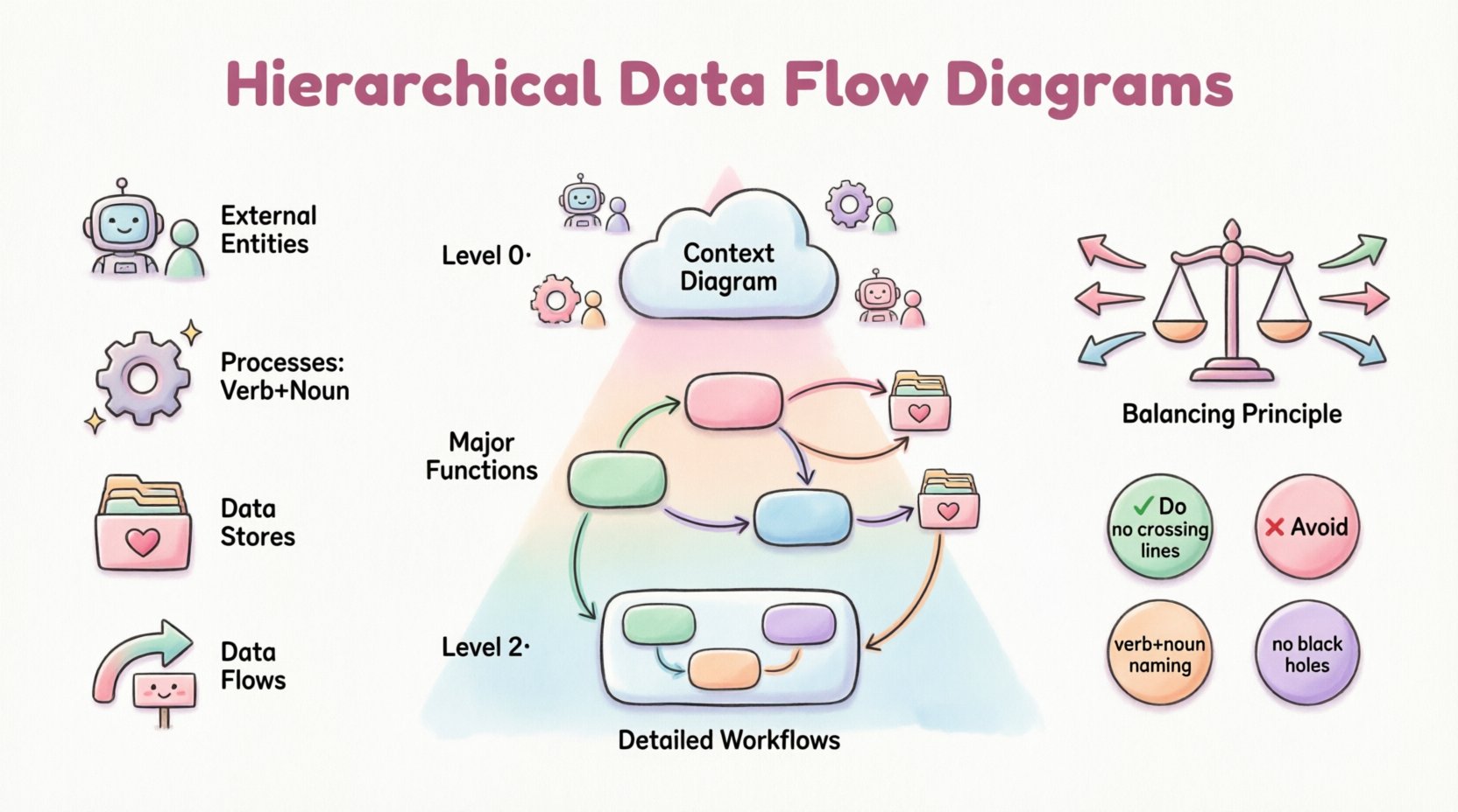
Deep Dive into Hierarchical Data Flow Diagrams

In the complex landscape of system analysis and software engineering, clarity is the most valuable asset. When dealing with intricate business processes or large-scale information systems, a single static map often fails to capture the necessary detail. This is where the Hierarchical Data Flow Diagram becomes indispensable. By breaking down complex systems into manageable layers, […]

UML

Common Mistakes in UML Component Diagrams: Preventing Over-Abstraction in Design Phases

Designing complex software systems requires a clear blueprint. Unified Modeling Language (UML) component diagrams serve as a critical tool for visualizing the structural organization of a system. They represent the physical or logical building blocks of software, showing how components interact, depend on one another, and provide functionality. However, creating these diagrams is not merely

UML

Case Study: Leveraging UML Activity Diagrams to Streamline CI/CD Pipeline Workflows

In the modern landscape of software development, the speed and reliability of delivery are paramount. Organizations strive to release features rapidly while maintaining high stability. However, as pipelines grow in complexity, visualizing the flow of code from commit to production becomes increasingly difficult. This is where Unified Modeling Language (UML) Activity Diagrams prove invaluable. By

UML

The Complete Component Breakdown of UML Class Diagrams for Intermediate System Analysts

System analysis requires precision. When modeling software architecture, clarity is paramount. Unified Modeling Language (UML) Class Diagrams serve as the structural blueprint for object-oriented systems. They define the static structure of a system, outlining objects, their attributes, methods, and relationships. For intermediate analysts, moving beyond basic shapes into semantic depth is essential. This guide dissects

UML

Comprehensive Walkthrough of UML Timing Diagrams: Syncing Events Across Global Systems

Designing software for global deployment introduces a unique set of challenges, primarily centered around time. In distributed systems, latency, clock drift, and network delays can cause critical failures if not properly modeled. A UML Timing Diagram offers a specialized view for visualizing how objects change state over time. Unlike other diagrams that focus on flow,

UML

Definitive Overview of UML Interaction Overview Diagrams: Handling Nonlinear Control Flow

In modern software architecture, systems rarely follow a straight line. User actions branch, conditions change, and error handling loops back to previous states. When modeling these complex behaviors, standard Sequence Diagrams often fall short because they assume a linear progression of messages. This is where the UML Interaction Overview Diagram becomes essential. It provides a

UML

Comparison of UML Profiles: Extending Standard Notation for Domain-Specific Architectures

The Unified Modeling Language (UML) serves as the foundational standard for software architecture. However, general-purpose modeling often falls short when addressing complex, specialized domains. This is where UML Profiles become essential. Profiles allow architects to extend the standard notation without altering the core specification. This guide explores how profiles enable domain-specific architectures, comparing standard extensions

UML

Common Mistakes in UML Activity Diagrams: Why Your Process Flows Are Confusing Stakeholders

Unified Modeling Language (UML) activity diagrams are powerful tools for visualizing the dynamic aspects of a system. They represent workflows, logic, and decision points in a graphical format that is often easier to digest than dense textual requirements. However, a diagram that is technically correct can still fail to communicate effectively. Many teams create activity

Scroll to Top