


Business process modeling relies heavily on the Unified Modeling Language (UML) to visualize workflows. Among the various UML diagrams, the Activity Diagram stands out as the primary tool for representing the dynamic behavior of a system. It maps out the flow of control from one activity to another, illustrating the sequence of operations required to achieve a specific business goal. However, a common pitfall in this modeling process is the introduction of logic loops that do not terminate. These infinite loops can render a process model invalid, leading to confusion during development and potential failures in the deployed system.
A robust UML Activity Diagram must accurately reflect the real-world constraints of the business process it represents. When a loop lacks a clear exit condition, it breaks the logical flow, creating a scenario where the process never completes. This guide provides a comprehensive checklist to ensure your diagrams are free from logical errors, specifically focusing on avoiding unintended logic loops.
🧩 Understanding the Foundations of Activity Diagrams
Before diving into the specific checklist for loop prevention, it is essential to understand the core components of an Activity Diagram. These diagrams are essentially flowcharts enhanced with specific UML semantics that define concurrency, decision making, and object flow.
Key Components
- Initial Node: Represented as a solid black circle, this is the starting point of the activity flow.
- Activity State: Represented as a rounded rectangle, this denotes a phase of work or a period of time during which an action is performed.
- Control Flow: Represented as an arrow, this indicates the order in which activities occur.
- Decision Node: Represented as a diamond, this allows for branching paths based on conditions.
- Fork and Join Nodes: Represented as thick horizontal or vertical bars, these manage the concurrency of activities.
- Final Node: Represented as a solid circle inside a larger circle, this marks the termination of the activity.
When constructing these diagrams, the integrity of the control flow is paramount. Every path initiated from the initial node must eventually lead to a final node. If a path leads into a cycle without a mechanism to exit, the model is technically flawed.
🔄 The Mechanics of Logic Loops
Loops are a necessary feature of process modeling. They represent iterations, such as retrying a failed transaction or processing a list of items until empty. However, there is a distinct difference between a controlled loop and an infinite logic loop.
Controlled vs. Uncontrolled Loops
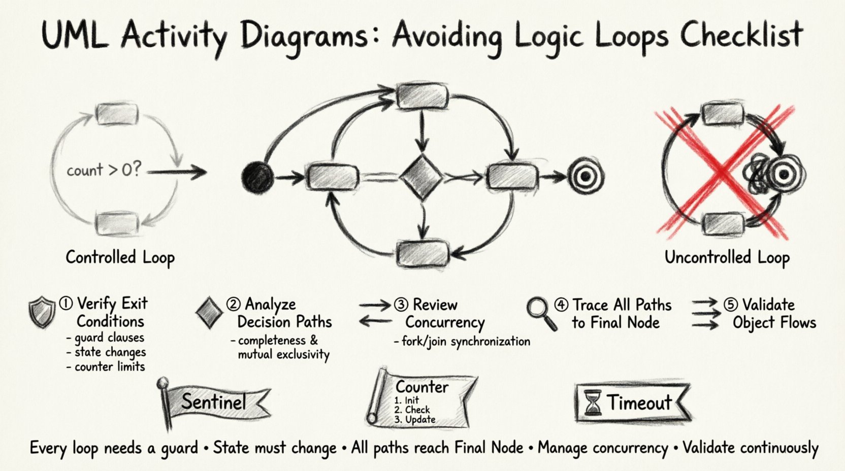
A controlled loop contains a specific guard condition that becomes false after a finite number of iterations. For example, a process might check if an inventory count is greater than zero before processing an item. Once the count reaches zero, the loop terminates.
An uncontrolled loop lacks this exit mechanism. This often happens when:
- The condition is always true.
- The condition is never evaluated.
- The variable controlling the condition is never updated.
- The path leads back to the start without passing through a decision node that alters the state.
In a business context, an infinite loop implies that a task will never be marked as “complete.” This results in system hangs, resource exhaustion, and data inconsistencies. Therefore, identifying and eliminating these loops is a critical quality assurance step.
✅ The Checklist for Loop Prevention
The following checklist serves as a verification tool for analysts and architects. Review each point systematically against your activity diagrams to ensure logical integrity.
1. Verify Exit Conditions
Every loop structure must have a definitive exit point. Do not rely on implicit assumptions. Ensure that the condition governing the loop is explicitly defined.
- Guard Clauses: Are there labels on the control flow edges entering and exiting the loop? For instance, label the path entering the loop as “True” or “Yes” and the path exiting as “False” or “No”.
- State Changes: Is there an activity within the loop that modifies the state variable used in the decision node? If the variable remains static, the loop will never end.
- Counter Limits: If the process involves counting (e.g., processing records), is there a maximum limit defined to prevent runaway scenarios?
2. Analyze Decision Node Paths
Decision nodes are the primary sources of branching and looping. Incorrectly placed decision nodes often create accidental cycles.
- Completeness: Do all outgoing paths from a decision node have conditions that cover all possible outcomes? A missing “Else” path can cause the flow to get stuck.
- Mutually Exclusive: Ensure that the conditions do not overlap in a way that allows multiple paths to be taken simultaneously unless intended.
- Single Entry, Single Exit: For simple loops, ensure there is only one entry point and one logical exit point to maintain clarity.
3. Review Concurrency Constructs
Fork and Join nodes introduce parallelism, which complicates loop detection. A thread might loop while another thread waits, or they might synchronize incorrectly.
- Join Synchronization: Does the Join node wait for all incoming threads? If one thread enters an infinite loop, the entire process stalls at the Join node.
- Thread Termination: Are there mechanisms to terminate parallel threads if the main process exits or fails?
- Data Sharing: Are shared variables between parallel activities updated safely? Race conditions can lead to unpredictable loop behavior.
4. Trace All Paths to Final Node
Perform a path traversal analysis. Start at the Initial Node and follow every possible arrow. Each path must terminate at a Final Node.
- Walkthrough: Manually trace the diagram. If you return to a previous node without a condition to break the cycle, mark it as a potential loop.
- Dead Ends: Check for paths that lead nowhere. While not loops, they indicate missing logic that might force a fallback into a loop.
- Exception Handling: Ensure error paths do not loop back to the start of the process without addressing the root cause.
5. Validate Object Flows
Activity diagrams often show object flows (data movement) alongside control flows. The lifecycle of an object can influence loop behavior.
- Object Creation: Is an object created inside the loop and never destroyed? This can lead to memory leaks in the implementation.
- Object Modification: Is the object being modified in a way that eventually satisfies the exit condition?
- Input Validation: Are inputs validated before entering the loop to prevent invalid data from triggering infinite retries?
📊 Common Pitfalls and Solutions Table
The table below summarizes common structural errors found in UML Activity Diagrams that result in logic loops, along with their corrective actions.
| Pitfall | Description | Corrective Action |
|---|---|---|
| Missing Decision Node | A control flow returns to a previous activity without a conditional check. | Insert a Decision Node before the return path to evaluate a termination condition. |
| Static Guard Condition | The condition on the loop edge never changes value during execution. | Ensure an activity within the loop modifies the variable used in the condition. |
| Unreachable Final Node | A loop exists that bypasses the Final Node entirely. | Rewire the flow to ensure the exit condition leads directly to the Final Node. |
| Concurrent Race Condition | Parallel threads modify a shared state inconsistently. | Implement synchronization locks or use local variables within the loop scope. |
| Implicit Retry Logic | Error handling loops back to the start without fixing the error. | Add a limit on retry attempts or a failure state that breaks the loop. |
🛠 Advanced Patterns for Loop Control
Beyond the basic checklist, advanced modeling techniques can further reduce the risk of logic errors. These patterns are particularly useful in complex business processes involving multiple departments or systems.
The Sentinel Pattern
Use a sentinel value to signal the end of a loop. In an activity diagram, this can be represented by a specific state or object that indicates completion. For example, a “Status” object transitions from “Processing” to “Complete”. The loop continues only while the Status is “Processing”. This makes the exit condition explicit and visible.
The Counter Pattern
For processes that iterate over a known set (e.g., a list of customers), use a counter. The activity diagram should show an increment action and a comparison action. The loop exits when the counter exceeds the total count. This prevents the model from assuming the list is infinite.
The Timeout Pattern
In systems where external dependencies might hang, include a timeout mechanism. The activity diagram should show a timer activity. If the timer expires before the task completes, the flow diverts to a failure or fallback path. This ensures the process does not hang indefinitely.
🔍 Validation Techniques
Once the diagram is drafted, validation is necessary to confirm the logic holds up under scrutiny.
Peer Review
Have a colleague review the diagram without looking at the code or specifications. Ask them to trace the flow. If they get stuck or ask “What happens if this is true?”, the diagram needs clarification.
Simulation
Use modeling tools to simulate the execution of the diagram. Input different data sets and observe the execution path. Check if the final node is reached for all valid inputs.
Code Walkthrough
Compare the activity diagram with the actual implementation code. The code should be a direct translation of the diagram. If the code has a `while(true)` loop that does not exist in the diagram, the diagram is incomplete. Conversely, if the diagram has a loop that is not in the code, the design is not being followed.
🚫 Implications of Logic Loops
Why is this checklist so critical? The consequences of ignoring logic loops extend far beyond the diagram itself.
- System Stability: Infinite loops consume CPU cycles and memory, potentially crashing the application.
- User Experience: Users may experience frozen interfaces or unresponsive services.
- Business Costs: Automated processes running in loops generate unnecessary transaction costs and resource usage.
- Data Integrity: Processes that loop may update records multiple times or fail to update them at all, leading to inconsistent data states.
- Security Risks: Denial of Service (DoS) attacks often exploit infinite loops to overwhelm system resources.
📝 Implementation Steps
To integrate this checklist into your workflow, follow these steps.
- Design Phase: Draft the activity diagram using standard UML notation.
- Self-Review: Apply the checklist items to your own work before sharing.
- Collaboration: Present the diagram to the development team for technical feasibility.
- Refinement: Update the diagram based on feedback, specifically regarding loop conditions.
- Final Sign-off: Ensure the Final Node is reachable from all paths before approving the design.
📈 Metrics for Quality Assurance
To track the effectiveness of your modeling efforts, consider the following metrics.
- Loop Density: The number of loops per diagram. High density requires stricter review.
- Path Coverage: The percentage of paths that successfully reach the Final Node.
- Defect Rate: The number of logic loop errors found during the development phase versus the design phase.
- Review Cycle Time: The time taken to resolve loop-related feedback during peer reviews.
🛡 Maintaining Diagram Integrity
As business processes evolve, the activity diagrams must be updated. A change in one part of the process can inadvertently introduce a loop elsewhere.
- Version Control: Keep track of changes to the diagrams. If a loop is introduced, revert or fix it immediately.
- Change Impact Analysis: Before modifying a diagram, analyze which paths connect to the loop areas.
- Documentation: Document the logic for complex loops. Explain why the loop exists and how it terminates.
📌 Summary of Key Takeaways
Creating accurate UML Activity Diagrams requires discipline and attention to detail. The primary goal is to ensure that every path leads to a completion state. By systematically applying the checklist provided, you can eliminate the risk of infinite logic loops.
Remember the following core principles:
- Every loop must have a guard condition.
- State must change within the loop to ensure termination.
- All paths must reach the Final Node.
- Concurrency must be managed to prevent deadlocks.
- Validation should be an ongoing process, not a one-time task.
By adhering to these standards, you ensure that your business process models are not just visual representations, but reliable blueprints for system implementation. This rigor reduces development errors and ensures that the software delivered matches the intended business logic.
Start applying this checklist to your next modeling project. Verify each node, trace each path, and ensure that your diagrams reflect a world where processes actually end.