


Creating a robust Data Flow Diagram (DFD) is a foundational step in system analysis and design. It serves as a visual blueprint, mapping how information moves through a system. However, a diagram without precise documentation is merely an illustration, not a functional specification. This guide provides a structured checklist to ensure your DFD documentation is accurate, complete, and ready for development teams.
Whether you are defining a new information system or auditing an existing architecture, clarity is paramount. The following sections detail the critical components, validation steps, and maintenance protocols required for professional-grade documentation.
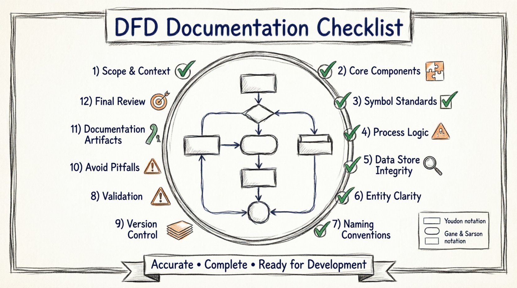
1. Defining the Scope and Context 🎯
Before drawing a single symbol, the boundaries of the system must be clearly established. Ambiguity here leads to scope creep and misaligned expectations.
System Boundary: Clearly distinguish between what is inside the system (the process) and what is outside (the environment).
Primary Actors: Identify the external entities interacting with the system. These are sources or sinks of data.
Goal Statement: Include a brief text description at the top of the diagram defining the system’s primary objective.
Level Identification: Specify whether this is a Context Diagram (Level 0) or a lower-level decomposition (Level 1, 2, etc.).
A well-defined context prevents the inclusion of unnecessary processes or missing external dependencies. Ensure the context diagram shows only one central process representing the entire system, connected to external entities.
2. Core Component Verification ✅
A DFD relies on four fundamental symbols. Each must be used correctly to maintain logical consistency.
External Entities (Squares/Rectangles)
Represent people, organizations, or external systems.
Never place an entity inside the system boundary.
Ensure every entity has at least one data flow entering or leaving the system.
Processes (Rounded Rectangles/Circles)
Represent transformations of data.
Every process must have at least one input and one output.
Avoid “Black Holes” (processes with only inputs) or “Miracles” (processes with only outputs).
Data Stores (Open Rectangles/Parallel Lines)
Represent places where data rests (databases, files, archives).
Ensure flows are bidirectional (read/write) if the store is updated, or unidirectional if it is read-only.
Never connect an external entity directly to a data store without a process in between.
Data Flows (Arrows)
Show the movement of data between components.
Label every arrow with a noun phrase describing the data content (e.g., “Invoice”, “User ID”).
Avoid generic labels like “Information” or “Data”.
3. Symbol Standardization 🧩
Different modeling conventions exist. The two most common are the Yourdon & DeMarco method and the Gane & Sarson method. Consistency is more important than the specific choice, but you must document which notation you are using.
Component | Yourdon & DeMarco | Gane & Sarson | Usage Rule |
|---|---|---|---|
Process | Circle | Rounded Rectangle | Choose one and stick to it. |
Data Store | Open Rectangle | Open Rectangle with vertical line | Ensure it looks distinct from a process. |
External Entity | Rectangle | Rectangle | Keep distinct from Data Stores. |
Data Flow | Curved Arrow | Straight Arrow | Label clearly. |
Documenting this choice in a legend or style guide section of your documentation prevents confusion during peer reviews.
4. Process Logic and Granularity 🔍
One of the most common errors in DFD creation is mixing levels of abstraction. A process box should represent a single logical function, not a complex workflow.
One Process, One Function: If a box describes “Process Order,” it should handle order processing. It should not also handle “Calculate Shipping” unless those are tightly coupled in the logic.
Decomposition: If a process is too complex to understand in one step, decompose it into a Level 1 DFD.
Input/Output Balance: Verify that every input data flow contributes to an output data flow.
Control Flows: Remember that DFDs do not show control logic (like loops or conditions). Those belong in flowcharts or decision tables. Do not annotate DFD arrows with “If X then Y”.
When reviewing your diagram, ask: “Can this process be explained in a single sentence?” If the answer is no, split the process.
5. Data Store Integrity 🗃️
Data stores are the memory of the system. Their documentation requires strict adherence to conservation of data.
Conservation of Data: All data entering a process must be accounted for in the output or stored. Do not lose data mid-process without logging it.
Read vs. Write: Ensure arrows entering a store indicate a write (update) operation, and arrows leaving indicate a read (retrieve) operation.
Storage Naming: Name data stores based on the content, not the technology (e.g., use “Customer Records” instead of “SQL_Table_01”).
Access Control: While DFDs do not show security permissions, ensure that sensitive data flows are noted in the accompanying text documentation.
A missing data store is a critical flaw. If data is saved, there must be a store. If data is read, there must be a source store.
6. External Entities Clarity 🚪
External entities define the interface of your system. They are the boundaries of your responsibility.
Consistency: Use the same name for an entity across all levels of the diagram.
Completeness: Ensure every entity that interacts with the system is represented.
Role Definition: Specify if an entity acts as a sender or receiver in the context of the specific flow.
Separation: Do not merge two distinct entities into one unless they always act in unison.
Common mistakes include treating a database as an external entity (it is an internal store) or treating a user role as a data store.
7. Labeling and Naming Conventions 🏷️
Naming conventions are the grammar of your diagram. They must be consistent, descriptive, and unambiguous.
Verb-Noun Pairs: Process names should always be Verb + Noun (e.g., “Validate Login”, “Generate Report”).
Noun Phrases: Data flow labels should be Noun Phrases (e.g., “Login Credentials”, “Monthly Report”).
Pluralization: Decide on a rule for singular vs. plural. “Customer” or “Customers”? Stick to one style throughout.
Avoid Abbreviations: Spell out terms unless they are industry-standard (e.g., “ID” is okay, “Amt” is risky).
Use a glossary section in your documentation to define specific terms used in the labels to ensure all stakeholders interpret them identically.
8. Validation and Cross-Referencing 🔗
A diagram must be validated against the requirements and other diagrams. Consistency across levels is non-negotiable.
Balancing: When decomposing a process, the inputs and outputs of the parent process must match the aggregate inputs and outputs of the child processes.
Traceability: Each process on the diagram should link to a requirement ID in the requirements document.
Review Cycle: Conduct a formal walkthrough with stakeholders to verify the logic matches their mental model of the system.
Completeness Check: Ensure every requirement is mapped to at least one process or data flow.
Validation Step | Question to Ask | Action if Failed |
|---|---|---|
Input/Output Check | Does every process have at least one input and one output? | Add missing flows or split the process. |
Entity Check | Are all external actors represented? | Add missing entities. |
Balance Check | Do child diagrams match parent inputs/outputs? | Adjust flows in child diagrams. |
Label Check | Are all flows labeled with data names? | Add descriptive labels. |
9. Maintenance and Version Control 🔄
Systems evolve, and diagrams must evolve with them. Static documentation becomes obsolete quickly without a maintenance strategy.
Versioning: Assign version numbers to your diagrams (e.g., v1.0, v1.1). Record the date of the last update.
Change Log: Maintain a log of what changed between versions. Note which processes were added, removed, or modified.
Accessibility: Store diagrams in a central repository accessible to developers and analysts.
Review Schedule: Schedule periodic reviews to ensure the diagrams still reflect the current system state.
Do not allow the diagram to drift from reality. If a feature is removed, remove it from the diagram immediately.
10. Common Pitfalls to Avoid ⚠️
Even experienced analysts fall into specific traps. Being aware of these common errors will save time during the review process.
Direct Entity to Entity Flows: Never draw a line directly from one external entity to another without passing through the system. This bypasses the system boundary.
Control Flow Confusion: Do not draw arrows representing triggers or timing. DFDs track data, not control signals.
Process to Process Flows: Ensure data flows between processes represent actual data transfer, not just a call or trigger.
Overcrowding: If a diagram has too many elements, split it into multiple levels. A Level 0 diagram should typically have between 7 and 9 processes.
Missing Data Stores: If data is created but not stored, it is lost. If data is stored, it must be retrievable.
11. Documentation Artifacts 📊
The diagram alone is not enough. The documentation package must support the visual representation.
Process Specifications: A detailed description of the logic inside each process box (often called a Process Specification or Mini-spec).
Data Dictionary: A comprehensive list of all data elements, including data types, formats, and allowed values.
Entity Descriptions: Profiles for each external entity, describing their role and relationship to the system.
Store Definitions: Detailed schema information for each data store.
These artifacts bridge the gap between the visual diagram and the technical implementation. They ensure that developers have the necessary detail to build the system accurately.
12. Final Review Checklist 🧾
Before submitting or publishing your DFD documentation, run through this final verification list.
Are all symbols consistent with the chosen notation?
Is every arrow labeled with a data name?
Is every process named with a Verb + Noun structure?
Do all external entities appear on the Context Diagram?
Is there a legend explaining the notation?
Are all processes balanced across decomposition levels?
Is there a change log and version number?
Is the data dictionary complete and referenced?
Completing this checklist ensures that the documentation is not just visually appealing, but technically rigorous and ready for implementation.