


The Unified Modeling Language (UML) has been a staple of software engineering discussions for decades. Yet, a persistent divide exists between how it is taught in academic settings and how it is applied in live production environments. Many practitioners view UML as an artifact of the past, a bureaucratic hurdle that slows down development. Others argue that without structured modeling, software architecture collapses into unmanageable complexity.
This guide cuts through the noise. It examines the actual utility of modeling notations, distinguishing between theoretical rigor and practical necessity. The goal is not to prove UML wrong or right, but to clarify when it serves a purpose and when it becomes an obstacle.
🏛️ The Academic Origin Story
UML emerged in the 1990s when three major methodologists—Booch, Rumbaugh, and Jacobson—merged their respective notations to create a standard. The intention was clear: provide a common language for developers, architects, and stakeholders. In academia, the focus often leans towards formal correctness, completeness, and strict adherence to syntax rules.
University courses frequently emphasize the creation of comprehensive documentation sets. Students are taught to model every class, every interaction, and every state transition before writing a single line of code. This approach mirrors the Waterfall methodology, where design precedes implementation. While this ensures a structured thought process, it often fails to translate to the iterative nature of modern engineering.
In the classroom, a diagram is a gradeable artifact. In the industry, a diagram is a communication tool. If a diagram cannot be read quickly or updated easily, its value drops significantly. The academic pressure for perfection often results in models that are too complex to maintain or too abstract to be useful.
🚫 Common Misconceptions About Modeling
Several myths surround the use of modeling languages. These misconceptions can lead to wasted effort or the rejection of useful practices. Addressing them helps clarify the actual role of diagrams in architecture.
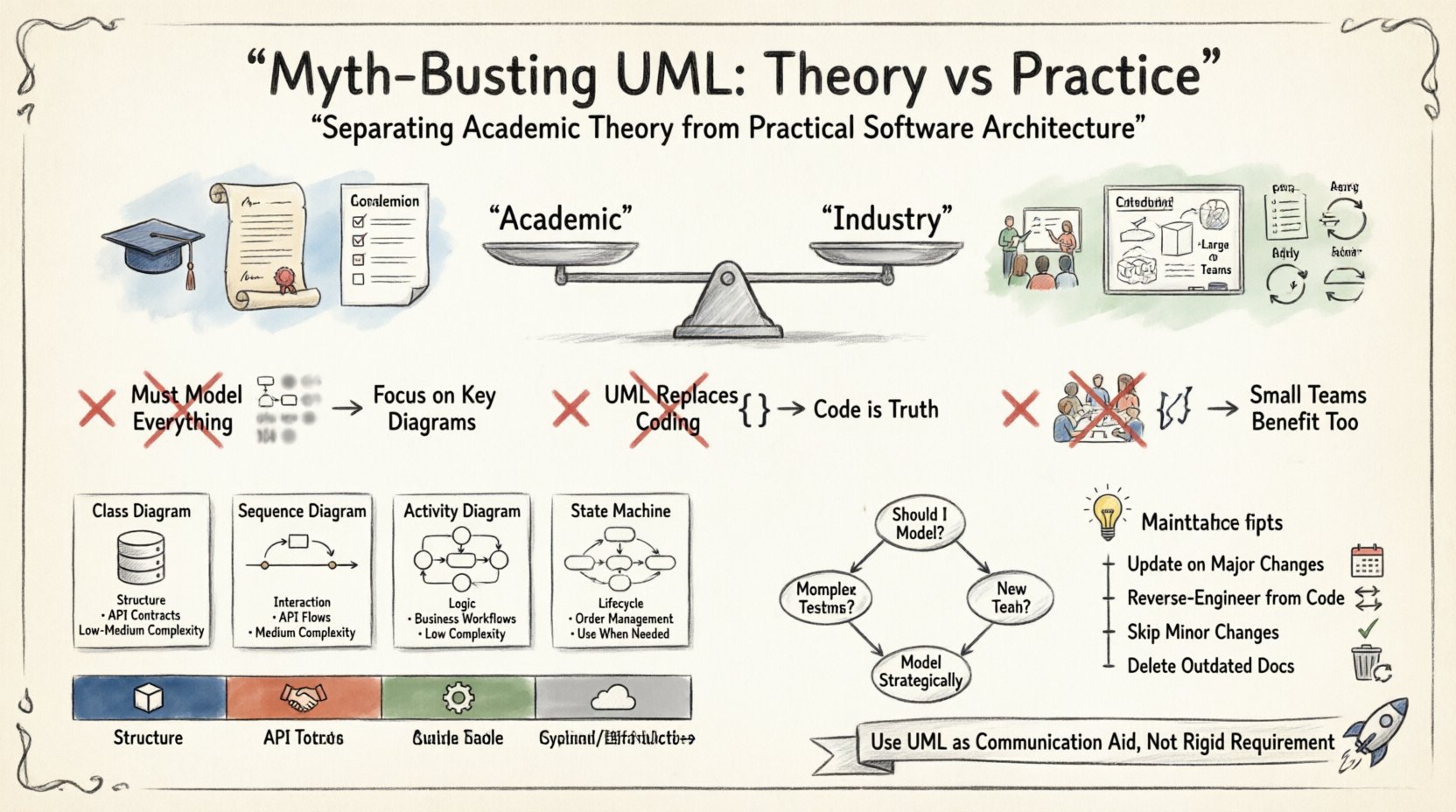
1. You Must Model Everything
A common belief is that a complete model requires every possible diagram type. This leads to “modeling for modeling’s sake.” In practice, a project rarely needs more than a handful of views to function effectively.
- Over-Engineering: Creating state diagrams for simple objects wastes time.
- Focus: It is better to have one clear sequence diagram than ten incomplete ones.
- Clarity: Simplicity aids understanding. Complex models often obscure the core logic.
2. UML Replaces Coding
Some argue that detailed models should be executable, generating the final code automatically. While code generation tools exist, relying on them exclusively is risky. Models are often abstractions that hide implementation details like performance constraints, memory management, or legacy integration.
- Code is Truth: The codebase is the only single source of truth that actually runs.
- Drift: Models often become outdated as soon as the code changes.
- Refactoring: Developers need to refactor code without necessarily updating every diagram.
3. It Is Only for Large Teams
There is a perception that UML is necessary only for massive organizations with hundreds of developers. However, small teams often face communication challenges that diagrams can solve.
- Knowledge Transfer: Diagrams help onboard new members faster than reading code alone.
- Visualizing Flow: It is easier to see data flow in a diagram than in a function call stack.
- Scope: Even a solo developer benefits from sketching architecture before starting.
🛠️ The Practical Toolkit
In a practical setting, the goal is communication, not documentation. You do not need to produce a full suite of diagrams. Instead, select the notation that best fits the problem at hand.
Class Diagrams: The Backbone
Class diagrams remain the most widely used type. They show static structure, relationships, and attributes. They are essential for defining the domain model.
- Use Case: Defining entity relationships in a database layer.
- Benefit: Helps identify normalization issues or circular dependencies.
- Limitation: Does not show behavior or timing.
Sequence Diagrams: The Flow
Sequence diagrams illustrate how objects interact over time. They are invaluable for understanding complex workflows.
- Use Case: Tracing a user login request through authentication, logging, and session creation.
- Benefit: Reveals hidden dependencies and potential bottlenecks.
- Limitation: Can become messy if the interaction path is too broad.
Activity Diagrams: The Logic
Activity diagrams look like flowcharts. They are useful for describing algorithms or business processes.
- Use Case: Visualizing a payment processing workflow with conditional branches.
- Benefit: Clarifies decision points and parallel processes.
- Limitation: Not suitable for object-oriented state management.
State Machine Diagrams: The Lifecycle
These diagrams show how an object changes state in response to events.
- Use Case: Managing the lifecycle of an order (Pending, Shipped, Delivered).
- Benefit: Prevents invalid state transitions in the code.
- Limitation: Can be overkill for simple objects.
📊 Comparison of Diagram Types
| Diagram Type | Primary Focus | Best Used For | Complexity Level |
|---|---|---|---|
| Class Diagram | Structure | Database Schema, API Contracts | Low to Medium |
| Sequence Diagram | Interaction | API Calls, Event Flows | Medium |
| Activity Diagram | Logic | Business Workflows | Low |
| Component Diagram | Decomposition | System Modules, Microservices | Medium |
| Deployment Diagram | Infrastructure | Server Setup, Cloud Architecture | High |
⚖️ Maintenance vs. Creation
One of the biggest friction points in software architecture is the cost of maintaining diagrams. In many projects, the model is created once and then ignored. This leads to a gap between the design and the implementation.
To avoid this, consider the following strategies:
- Update on Change: Require model updates only when the architecture changes significantly, not for every code commit.
- Visual Code Generation: Use tools that can reverse-engineer code into diagrams. This keeps the model synchronized with the source.
- Skip the Diagram: If a change is minor, skip the diagram. Documentation should be proportional to the complexity of the change.
- Living Documentation: Treat diagrams as living assets. If they become outdated, delete them rather than maintaining false information.
The cost of a stale diagram is higher than the cost of not having one. A stale diagram misleads stakeholders and erodes trust in the documentation process.
🔄 UML in Modern Development Cycles
Agile methodologies emphasize working software over comprehensive documentation. This often puts UML in a difficult position. However, agile teams can still benefit from lightweight modeling if applied correctly.
Integration with Sprint Planning
During sprint planning, architects can sketch high-level sequence diagrams to clarify requirements. These do not need to be formal. They serve as a shared understanding tool.
- Quick Sketching: Use whiteboards or simple digital tools to map out flows.
- Refinement: Only formalize diagrams for complex subsystems.
- Review: Use diagrams during code review to ensure the implementation matches the design intent.
DevOps and Infrastructure
As infrastructure becomes code, the need for modeling shifts. Deployment diagrams help visualize how services connect across cloud environments. They are critical for understanding failure modes.
- Service Mesh: Diagrams show how traffic is routed between microservices.
- Security: Visualize data flow to identify security boundaries and encryption points.
- Scaling: Model horizontal scaling strategies to anticipate resource needs.
🤔 Decision Framework
When faced with the decision to model, ask specific questions. This prevents unnecessary work and ensures effort is spent where it matters.
- Is the system complex? High complexity benefits more from visual aids.
- Are there multiple teams? Cross-team coordination requires a shared vocabulary.
- Is the team new? New teams need documentation to accelerate onboarding.
- Is the technology stable? If the stack is changing frequently, modeling may be wasted effort.
Consider the trade-off between the time spent creating the diagram and the time saved by understanding the system.
📝 Academic Focus vs. Practical Focus
| Aspect | Academic Focus | Practical Focus |
|---|---|---|
| Completeness | High | Low to Medium |
| Accuracy | Strict Syntax | Logical Consistency |
| Update Frequency | End of Project | Continuous or On-Demand |
| Tooling | Formal Modeling Tools | Whiteboards, Sketching, Light Tools |
| Goal | Proof of Concept | Communication & Clarity |
Understanding this distinction helps teams align their expectations. It is acceptable to deviate from strict standards if the communication goal is met.
🚀 Final Thoughts
The debate over UML is not about the notation itself, but about the intent behind its use. When treated as a rigid requirement, it becomes a burden. When treated as a communication aid, it becomes a powerful asset.
Architects must balance the need for structure with the need for speed. The best approach is often a hybrid one. Use standard notations where they add value, but remain flexible enough to adapt to the project’s specific context. Documentation should support the work, not dictate it.
By separating academic theory from practical needs, teams can avoid the pitfalls of over-documentation while retaining the benefits of clear architectural thinking. The focus should remain on building robust, maintainable systems, using modeling only when it serves that end.