


Visualizing how software components communicate is a critical skill for any technical architect or developer. UML Sequence Diagrams serve as the blueprint for understanding the dynamic behavior of a system over time. They provide a clear, chronological view of object interactions, ensuring that every message sent and response received is accounted for. This guide breaks down the essential elements, syntax, and best practices required to create effective diagrams without confusion or ambiguity. 🚀
Understanding the Core Purpose of Sequence Diagrams 🎯
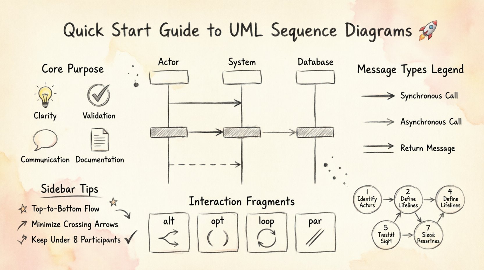
At its foundation, a sequence diagram maps the flow of control and data between objects. Unlike class diagrams which show static structure, sequence diagrams focus on runtime behavior. They answer the question: “What happens when this specific action is triggered?” This visualization helps teams align on logic before a single line of code is written.
- Clarity: Reduces ambiguity in complex workflows.
- Validation: Helps verify that requirements are met through interaction.
- Communication: Bridges the gap between business logic and technical implementation.
- Documentation: Serves as living documentation for future maintenance.
When used correctly, these diagrams prevent scope creep and ensure that edge cases are considered during the design phase. They are not merely drawings; they are logical contracts between system parts.
Essential Components Explained 🧩
To construct a meaningful diagram, one must understand the fundamental building blocks. Each element carries specific meaning regarding the state and behavior of the system. Skipping components often leads to incomplete documentation.
1. Participants (Lifelines) 👤
A participant represents an object, role, or system that participates in the interaction. These are depicted as vertical lines extending downwards from a box at the top. The vertical line is known as the lifeline, representing the existence of the participant over time.
- System Boundary: Can be used to group related objects.
- External Actor: Represents users or external services outside the system.
- Internal Object: Represents classes or modules within the application.
2. Messages 💬
Messages indicate communication between participants. They are drawn as horizontal arrows. The direction of the arrow indicates the sender and the receiver.
- Synchronous: The sender waits for the receiver to complete the task.
- Asynchronous: The sender continues immediately after sending the message.
- Return Message: Indicates a response from the receiver back to the sender.
3. Activation Bars 📊
Also known as execution occurrences, activation bars appear on the lifeline. They indicate the period during which an object is performing an action or is in control of the process. A long bar implies a complex operation, while a short bar suggests a quick method call.
Message Types and Syntax ➡️
Distinguishing between different types of messages is crucial for accurate modeling. The arrow style conveys the timing and nature of the interaction. Below is a breakdown of standard notations.
| Message Type | Arrow Style | Behavior Description |
|---|---|---|
| Synchronous Call | Solid line, filled arrowhead | Sender blocks until receiver finishes processing. |
| Asynchronous Call | Solid line, open arrowhead | Sender sends message and proceeds without waiting. |
| Return Message | Dashed line, open arrowhead | Response sent back to the original caller. |
| Self-Call | Loop arrow on the same lifeline | Object calls a method on itself. |
Timing and Labels
Labels on arrows should be concise but descriptive. Use verb phrases like requestLogin() or validateOrder(). If timing is critical, add timestamps or durations. However, avoid cluttering the diagram with excessive text. The goal is readability.
Interaction Fragments for Logic 🧠
Real-world scenarios rarely follow a straight line. Branching logic, loops, and optional steps are common. UML provides Interaction Fragments to handle these complexities. These are enclosed in a box with a label indicating the fragment type.
| Fragment | Label | Function |
|---|---|---|
| Alt | alt | Alternative paths (If/Else logic). |
| Opt | opt | Optional interaction (If condition met). |
| Loop | loop | Repeated interaction (For/While loops). |
| Break | break | Termination of a loop or process. |
| Par | par | Parallel execution of independent messages. |
| Ref | ref | Reference to another sequence diagram. |
Using these fragments correctly allows you to model complex algorithms without creating a spaghetti-like web of arrows. For example, an alt fragment is perfect for showing login success versus failure paths.
Constructing a Diagram: A Logical Flow 🛠️
Building a sequence diagram is a systematic process. Rushing through the steps often results in missing details. Follow this structured approach to ensure completeness.
- Define the Scenario: Identify the specific use case or user story you are documenting. Is it a login flow? A payment transaction?
- Identify Participants: List all objects, actors, and systems involved. Place them at the top in the order of interaction.
- Draw Lifelines: Extend vertical lines down from each participant. Ensure they are evenly spaced.
- Add Messages: Draw horizontal arrows representing the flow of data. Start with the initiating event.
- Insert Activation Bars: Mark where objects are active. This shows processing time clearly.
- Apply Fragments: Add alt, loop, or opt frames where logic branches or repeats.
- Review: Check for orphaned messages or missing return paths.
Common Patterns in Software Design 🏗️
Certain interaction patterns appear repeatedly across different applications. Recognizing these patterns saves time and ensures consistency.
1. The Request-Response Pattern
This is the most common interaction. A client sends a request, waits for a response, and processes the result. It is essential to show the return message clearly, even if it is null.
- Client sends
getData(). - Server processes request.
- Server returns
dataResult.
2. The Error Handling Pattern
Systems must handle failures gracefully. Use an alt fragment to show the success path versus the error path. This ensures developers know how to handle exceptions.
- Attempt operation.
- If Success: Return result.
- If Failure: Log error, notify user.
3. The Iteration Pattern
When processing collections, a loop is necessary. Enclose the interaction in a loop frame. Specify the condition, such as for each item, to make the logic explicit.
Maintaining Readability and Standards 📏
A diagram that is hard to read provides no value. Adhere to these standards to keep your documentation clean.
- Top-to-Bottom Flow: Time always moves downwards. Do not mix up the order.
- Minimize Crossing: Arrange participants so arrows do not cross unnecessarily. This improves visual scanning.
- Consistent Naming: Use standard naming conventions for methods and objects. Avoid abbreviations that are not universally understood.
- Scope Limitation: If a diagram becomes too large, split it into multiple diagrams. Use the ref fragment to link them.
- White Space: Leave enough space between messages to allow for annotations or future additions.
Common Mistakes and Corrections 🛑
Even experienced modelers make errors. Being aware of common pitfalls helps you avoid them.
- Mixing Static and Dynamic: Do not put class attributes inside a sequence diagram. Keep state changes to messages.
- Overloading Messages: Avoid putting too much logic inside a single arrow. Break complex operations into smaller steps.
- Ignoring Time: While exact timestamps are rare, the relative order must be accurate. Ensure synchronous calls wait for responses.
- Missing Returns: Every call should generally have a corresponding return arrow, even if it is just an acknowledgment.
- Too Many Participants: If you have more than 8 participants, consider grouping them or splitting the scenario.
Integrating Diagrams into Documentation 📝
Sequence diagrams should not exist in isolation. They are part of a larger documentation suite. Link them to use cases, user stories, and API specifications.
- Version Control: Treat diagrams as code. Store them in your repository and track changes.
- Living Documents: Update diagrams when requirements change. An outdated diagram is worse than no diagram.
- Accessibility: Ensure all team members can view and interpret the diagrams without specialized tools.
- Context: Always provide a brief text description alongside the diagram to explain the business context.
Advanced Considerations for Complex Systems 🔍
As systems grow, so does the complexity of interactions. Advanced modeling techniques help manage this growth.
1. Nested Frames
You can nest interaction frames within other frames. For instance, a loop inside an alternative path. This allows for highly granular control flow representation. However, keep nesting to a minimum to prevent visual confusion.
2. Time Constraints
In real-time systems, timing is critical. You can specify time limits on messages or activation bars. This indicates that a response must occur within a specific duration to maintain system integrity.
3. Object Creation and Destruction
Lifelines represent the lifecycle of objects. You can mark the start and end of a lifeline to show when an object is created or destroyed. This is vital for memory management understanding.
Final Thoughts on Effective Modeling 💡
Creating UML Sequence Diagrams is about clarity and precision. It requires a deep understanding of the system’s logic and the ability to translate that logic into a visual format. By following standard notations, avoiding common pitfalls, and maintaining a focus on readability, you can create diagrams that serve as powerful tools for development and maintenance.
Remember, the goal is not to create art, but to communicate logic. Keep the diagrams simple, accurate, and up to date. When your team can look at a diagram and immediately understand the flow of data, you have achieved a high standard of system design. Use these diagrams to facilitate discussion, catch errors early, and build robust software architectures.