


In the landscape of Model-Driven Architecture (MDA), the bridge between design and implementation relies heavily on the fidelity of the Unified Modeling Language (UML) specifications. When developers transition from abstract diagrams to concrete executable code, the margin for error narrows significantly. A single inconsistency in a class diagram can cascade into compilation failures or logical defects in the runtime environment. Therefore, a rigorous validation process is not merely a procedural step; it is a critical quality gate.
This guide outlines a comprehensive validation protocol for UML models. It focuses on structural integrity, semantic accuracy, and readiness for automated transformation. By adhering to these standards, teams can minimize technical debt and ensure that the generated code aligns precisely with the architectural vision.
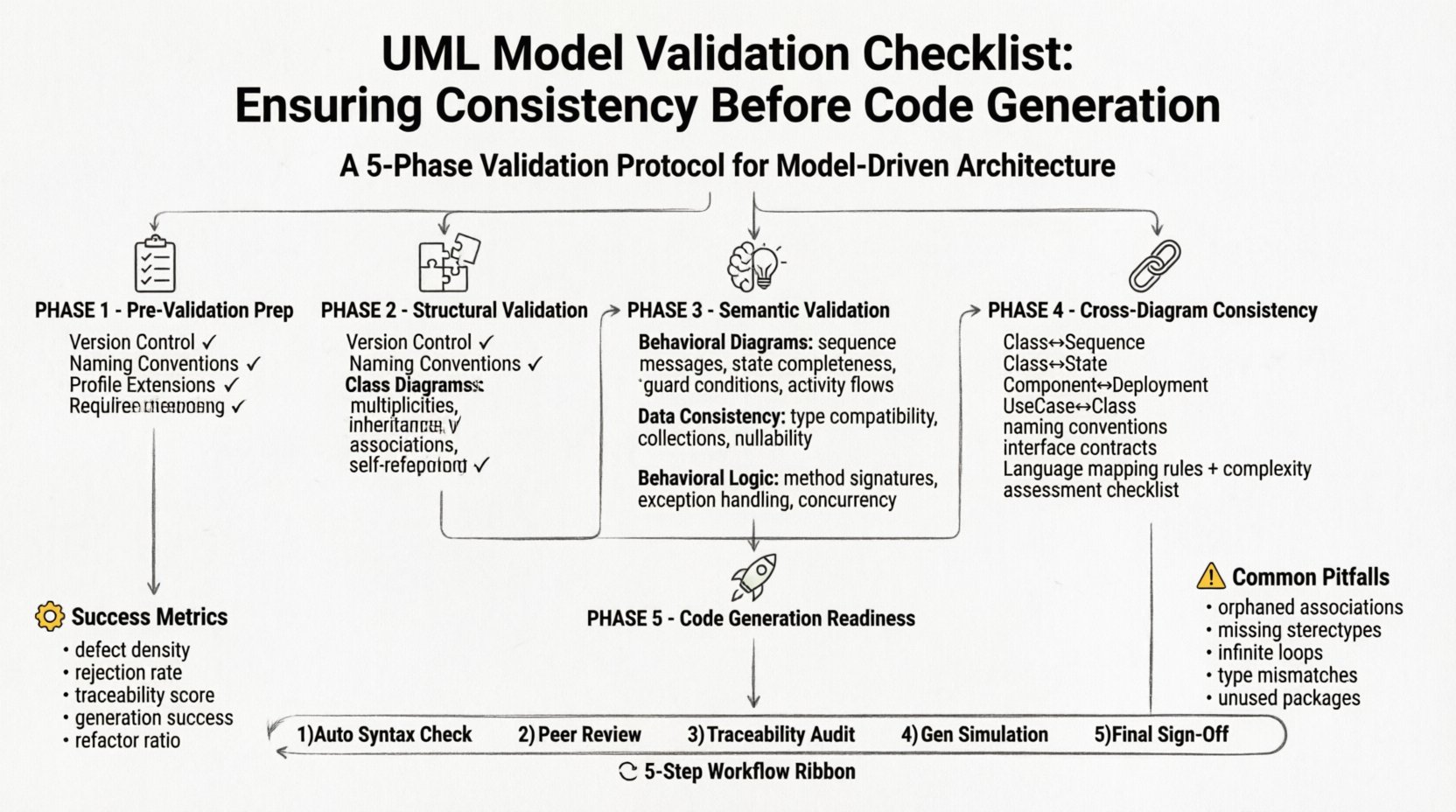
🔍 Pre-Validation Preparation
Before diving into specific diagram checks, the environment and documentation must be aligned. Validation is not an isolated event but a phase within a broader development lifecycle.
- Version Control: Ensure all model files are committed to a version control system. This allows for rollback capabilities if validation reveals critical flaws.
- Standard Definitions: Define and enforce naming conventions. A class named
userin one diagram andUserAccountin another creates ambiguity for code generators. - Profile Extensions: If using UML profiles (e.g., for specific frameworks), verify that all stereotypes are correctly defined and available to the validation engine.
- Requirement Mapping: Ensure that every diagram element traces back to a requirement ID. If a class exists without a requirement link, its necessity is questionable.
🧩 Structural Validation: Syntax and Grammar
The first layer of validation addresses the syntax of the model. UML has strict rules regarding how elements connect. Violating these rules often prevents the model from being parsed by code generation tools.
1. Class and Component Diagrams
- Multiplicity Constraints: Verify that associations have defined multiplicities (e.g., 0..1, 1..*, 0..*). Ambiguous relationships like “many” without bounds can lead to array sizing errors in generated code.
- Inheritance Hierarchies: Check for multiple inheritance where the target language only supports single inheritance. Ensure interfaces are used correctly to mimic interface behavior if the language restricts class inheritance.
- Attribute Visibility: Confirm that visibility modifiers (
public,private,protected,package) are explicitly set. Default settings may not map correctly to language-specific accessors. - Association Ends: Ensure every association end has a role name. Missing role names can result in generic variable names in the generated source code.
- Self-References: Validate recursive associations (e.g., a
Nodereferencing anotherNode). The generated code must handle circular references or pointers correctly.
2. Behavioral Diagrams
- Sequence Diagram Messages: Every message must have a defined source and target. Ensure that asynchronous vs. synchronous calls are marked correctly, as this affects threading models in the output.
- State Machine Completeness: Check for “dead states” where no transition is defined. Ensure that all states have exit conditions.
- Guard Conditions: Verify that guard conditions on transitions cover all logical possibilities. Missing guards can lead to unhandled exceptions at runtime.
- Activity Diagram Flows: Ensure that control flows do not cross without explicit merge nodes. Fanning out and fanning in must be balanced to maintain logic flow.
⚖️ Semantic Validation: Logic and Meaning
Syntax ensures the model is readable; semantics ensure the model is correct. A diagram can be syntactically perfect but logically flawed.
1. Data Consistency
- Type Compatibility: Verify that the data types used in associations match the target language’s capabilities. For example, a UML “Integer” might map to
intin C++ orIntegerin Java. Ensure these mappings are explicit. - Collection Types: Check if attributes are defined as single values or collections. Code generators often struggle to distinguish between a list and a single object without explicit stereotypes.
- Nullability: Define nullability constraints. Should an attribute be optional or mandatory? This dictates whether the generated constructor requires arguments.
2. Behavioral Logic
- Method Signatures: Ensure method signatures in class diagrams match the operations defined in sequence diagrams. A mismatch here causes compilation errors.
- Exception Handling: Check if exceptions are modeled. If a sequence diagram shows an error path, the generated code should include try-catch blocks or error handling logic.
- Concurrency: If the model implies parallel execution, verify that the state machines or activity diagrams define thread safety mechanisms or locks.
🔗 Cross-Diagram Consistency
UML models consist of multiple views. Inconsistencies between these views are a common source of bugs. Validation must occur across the entire suite of diagrams.
| Diagram Pair | Validation Focus | Potential Risk |
|---|---|---|
| Class & Sequence | Method existence and parameter types | Undefined method errors at runtime |
| Class & State Machine | Trigger events and state entry/exit actions | Unhandled state transitions |
| Component & Deployment | Interface realization and physical mapping | Linking failures in distributed systems |
| Use Case & Class | Actor responsibilities mapped to class methods | Missing functionality in implementation |
When validating cross-diagram consistency, look for orphaned elements. A class referenced in a sequence diagram but missing from the class diagram indicates a gap in the design.
1. Naming Conventions Across Views
- Global Uniqueness: Ensure entity names are unique across all diagrams. Avoid overloading names for different concepts.
- Consistent Abbreviations: If
usris used for “user” in one diagram, do not switch touin another. - Package Structure: Verify that the package hierarchy in the class diagram matches the namespace structure required by the code generator.
2. Interface Contract Validation
- Provided vs. Required: In component diagrams, check that provided interfaces are actually implemented by the component.
- Parameter Alignment: Ensure that the interface signature matches the implementation in the class diagram exactly.
- Directionality: Verify that the direction of the interface usage (call vs. callback) is consistent.
📏 Traceability and Requirements
Validation is incomplete without linking the model to the requirements. This ensures that the code being generated solves the actual problem.
- Requirement Coverage: Run a query to identify requirements without corresponding model elements. These represent scope creep or missing features.
- Element Coverage: Identify model elements that do not trace to any requirement. These are candidates for removal or refactoring.
- Impact Analysis: If a requirement changes, trace the impact through the model to all affected diagrams.
- Documentation Links: Ensure that detailed specifications are linked to the relevant model elements, especially for complex algorithms.
🚀 Code Generation Readiness
The final stage of validation assesses whether the model is suitable for transformation. Code generators have specific limitations and expectations.
1. Language Mapping Rules
- Enum Support: Verify that enumeration types are defined in a way the target language supports. Some languages require specific syntax for enums that UML does not inherently enforce.
- Nullable Types: Check if the target language handles nullability strictly (e.g., Kotlin or Scala) versus loosely (e.g., Java or C#). Adjust model constraints accordingly.
- Interface vs. Abstract Class: Decide if polymorphism should be modeled as an interface or an abstract class based on the target language’s capabilities.
2. Complexity Assessment
- Cyclomatic Complexity: Review complex state machines or activity diagrams. If a logic path is too deep, the generated code may become unreadable or unmaintainable.
- Recursive Structures: Limit the depth of recursive data structures. Deep recursion can cause stack overflow errors in generated code.
- Performance Constraints: If performance is critical, validate that the model does not imply unnecessary object creation or excessive copying.
🛡️ Common Validation Pitfalls
Avoiding common mistakes saves significant time during the implementation phase. The following table summarizes frequent issues encountered during model validation.
| Pitfall | Description | Remediation |
|---|---|---|
| Orphaned Associations | Links exist without defined ends | Assign role names and multiplicities to all ends |
| Missing Stereotypes | Custom types lack defined stereotypes | Define profiles and apply stereotypes explicitly |
| Infinite Loops | State machines lack exit paths | Add default transitions or timeout events |
| Type Mismatches | Parameter types do not match definition | Standardize primitive type definitions |
| Unused Packages | Namespace folders contain no classes | Remove empty packages or move classes to correct namespace |
📋 The Validation Workflow
To operationalize this checklist, integrate the following workflow into the development pipeline.
- Step 1: Automated Syntax Check
- Run static analysis tools to verify UML grammar.
- Resolve all syntax errors before manual review.
- Step 2: Peer Review
- Have a second architect review the diagrams for semantic clarity.
- Focus on business logic representation rather than syntax.
- Step 3: Traceability Audit
- Verify the matrix between requirements and model elements.
- Ensure 100% coverage of high-priority requirements.
- Step 4: Code Generation Simulation
- Run the generator in a dry-run mode.
- Inspect the generated artifacts for logical gaps.
- Step 5: Final Sign-Off
- Formal approval from the lead architect.
- Lock the model version for generation.
📊 Metrics for Validation Success
To measure the effectiveness of the validation process, track the following metrics.
- Defect Density: Number of defects found in the generated code per 1,000 lines of model.
- Rejection Rate: Percentage of model versions rejected during the validation phase.
- Traceability Score: Percentage of model elements linked to a requirement.
- Generation Success Rate: Percentage of generation runs that complete without errors.
- Refactor Ratio: Frequency of changes required to the model after initial validation.
🔧 Managing Evolution
Models evolve. Requirements change. The validation checklist must be applied iteratively, not just once.
- Incremental Updates: When a requirement changes, re-validate only the affected sub-graph of the model.
- Regression Testing: After model changes, re-run the full validation suite to ensure no new inconsistencies were introduced.
- Documentation Updates: If the model changes, ensure the accompanying documentation is updated simultaneously.
- Tooling Integration: Integrate validation rules into the IDE or modeling tool to provide real-time feedback.
🎯 Final Thoughts on Model Fidelity
The quality of the generated code is directly proportional to the quality of the model. A model that is vague, inconsistent, or incomplete will inevitably produce code that is brittle, unmaintainable, or incorrect. By treating the model as the source of truth and applying rigorous validation steps, teams can trust the transformation process.
Consistency is not a one-time achievement. It is a discipline maintained through every iteration. Following this checklist ensures that the bridge between design and code remains strong, allowing developers to focus on logic and implementation rather than debugging structural errors.
Invest time in the model. The return on investment appears in the stability of the final software product.