


In the architecture of complex software systems, understanding how components interact is paramount. As monolithic applications grow, the internal web of relationships becomes a critical factor in maintainability and stability. This guide explores the mechanics of UML package dependencies and provides a structured approach to visualizing coupling within large-scale environments.
Software systems are not merely collections of code; they are ecosystems of logical groupings. When these groupings, known as packages, interact, they form dependencies. Without clear visualization, these dependencies can evolve into a tangled mess that hinders development. By leveraging UML package diagrams, architects can map these relationships explicitly.
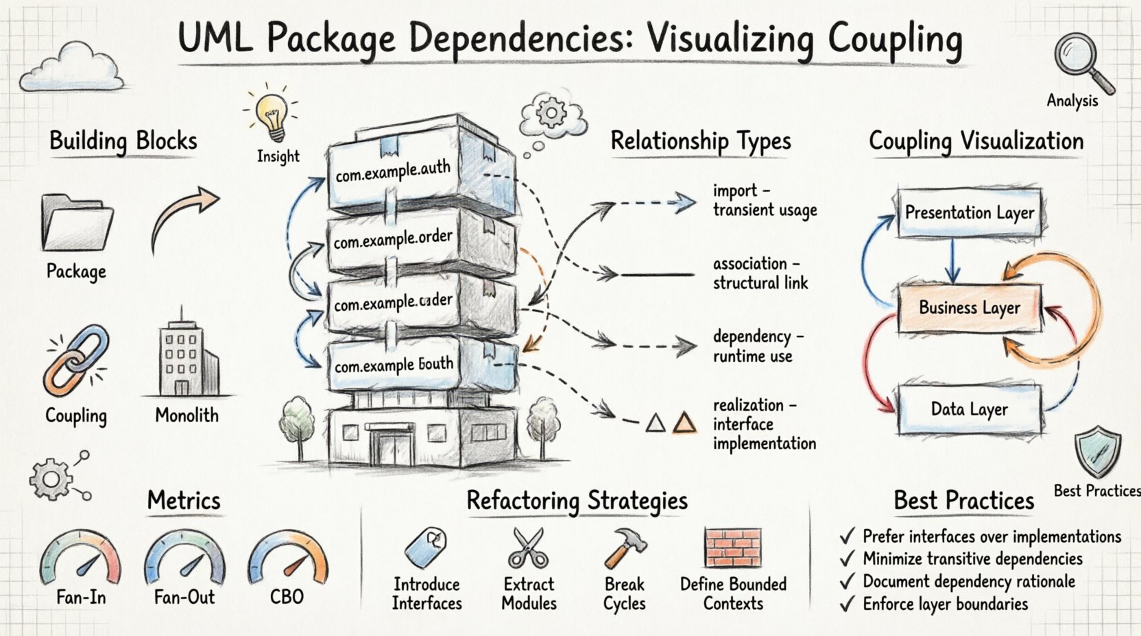
🏗️ Understanding the Building Blocks: Packages and Dependencies
Before analyzing coupling, one must define the fundamental units. A package in UML acts as a namespace. It groups related elements such as classes, interfaces, and other packages. This grouping provides logical organization, making large systems readable.
Dependencies represent a relationship where a change in one element might affect another. In the context of packages, this implies that the implementation of one package relies on the interface or structure of another.
Key Concepts Defined
- Package: A logical grouping of model elements. It serves as a container for organization.
- Dependency: A relationship indicating that one element requires knowledge of another to function correctly.
- Coupling: The degree of interdependence between software modules. High coupling means changes ripple easily; low coupling allows for isolated changes.
- Monolith: A single, unified unit of software. While simpler to deploy initially, large monoliths suffer from high internal coupling over time.
🔗 Types of Relationships in UML Package Diagrams
Not all dependencies are created equal. Distinguishing between them helps in assessing the risk of modifying a specific part of the system. UML defines specific stereotypes to denote these relationships.
1. Import Relationship
An import relationship allows the contents of a package to be visible within another package. This is often used when a package needs to expose its public interface to others without necessarily creating a direct dependency on every internal class.
2. Association Relationship
While often used for class diagrams, associations can exist between packages to indicate a structural link. This suggests that instances of elements in one package hold references to instances in another.
3. Dependency Relationship
This is the most common form of coupling. It indicates that a change in the supplier package might require a change in the client package. It is typically represented by a dashed line with an open arrow.
4. Realization Relationship
Used when a package implements an interface defined in another package. This is crucial for defining contracts that separate the client from the implementation.
| Type | Strength | Visibility | Use Case |
|---|---|---|---|
| Import | Medium | High (Public) | Sharing common definitions |
| Association | High | Variable | Direct object interaction |
| Dependency | Medium | Low | Usage of methods or attributes |
| Realization | High | Interface Only | Implementing contracts |
📉 Visualizing Coupling in Large-Scale Monoliths
In a monolithic architecture, packages are often layered. A typical structure includes Presentation, Business Logic, and Data Access layers. Visualizing how these layers interact reveals the health of the architecture.
Layering and Cross-Cutting
Strict layering dictates that a lower layer should not depend on a higher layer. However, in practice, violations occur. A common issue is the Business Logic layer directly accessing the Database package, bypassing the Data Access abstraction.
- Vertical Coupling: Dependencies flowing from top to bottom (Presentation to Data).
- Horizontal Coupling: Dependencies flowing between peers (e.g., Authentication package calling Billing package).
- Circular Coupling: Package A depends on Package B, and Package B depends on Package A. This creates a cycle that prevents independent testing or deployment.
The Impact of Hidden Dependencies
Dependencies often hide behind generic interfaces. A package might seem independent, but it relies on a specific implementation in another package. This creates a “hidden coupling” that is only visible during runtime or deep static analysis.
UML package diagrams help expose these hidden links. By forcing the architect to draw the dependency, the hidden coupling becomes explicit. This visibility is the first step toward management.
📊 Analyzing Coupling Metrics
Qualitative analysis is useful, but quantitative metrics provide concrete data. Several metrics help determine if a package is too coupled.
Fan-Out
Fan-out measures the number of other packages a specific package depends upon. A high fan-out suggests that the package is doing too much or is poorly encapsulated.
- Low Fan-Out: The package is cohesive and focused.
- High Fan-Out: The package relies on many external systems, making it fragile.
Fan-In
Fan-in measures how many other packages depend on the current package. High fan-in indicates a core utility or a critical service.
- High Fan-In: Generally desirable for core libraries, but changes must be handled with extreme care.
- Low Fan-In: The package might be redundant or overly specific.
Coupling Between Object Modules (CBO)
This metric counts the number of other modules a module depends on. In the context of packages, it aggregates the dependencies of all classes within the package.
🛠️ Strategies for Refactoring Coupled Monoliths
Once dependencies are mapped, the goal is often to reduce coupling. Refactoring should be approached methodically to avoid breaking existing functionality.
1. Introduce Interfaces
Replace direct dependencies on concrete classes with dependencies on interfaces. This decouples the client from the specific implementation details of the supplier package.
2. Extract Core Modules
Identify packages with high fan-in and low fan-out. These are candidates for extraction into a shared library or a separate microservice. This reduces the size of the monolith and isolates the core logic.
3. Break Circular Dependencies
Circular dependencies are architectural deadlocks. To resolve them:
- Move the shared code to a new, neutral package.
- Use dependency inversion to reverse the direction of the dependency.
- Redefine the boundary between the two packages.
4. Enforce Layer Boundaries
Implement strict rules where the Build System or Linter can prevent a package from importing another package it shouldn’t. For example, the Data Access layer should never import the Presentation layer.
🚧 Common Pitfalls in UML Modeling
Creating the diagram is only half the battle. Many teams fall into traps that render the diagrams useless.
Pitfall 1: Outdated Diagrams
If the code changes and the diagram does not, the diagram becomes a lie. It is better to have no diagram than a misleading one. Automated generation tools can help keep diagrams synchronized with the codebase.
Pitfall 2: Over-Granularity
Modeling every single class in a package diagram creates noise. Focus on the package level relationships. Individual class relationships belong in class diagrams.
Pitfall 3: Ignoring Runtime Dependencies
Static analysis shows compile-time dependencies. However, dynamic dependencies (like service discovery or configuration loading) might exist. These should be noted in the documentation even if they do not appear in the static UML.
🛡️ Best Practices for Documentation
Documentation serves as the contract between teams. Clear UML package diagrams serve as a shared language.
Standardizing Notation
Ensure all architects use the same notation for dependencies. Avoid mixing UML standards with proprietary symbols. Consistency reduces cognitive load for anyone reading the architecture.
Version Control
Treat architecture diagrams as code. Store them in the same repository as the source code. This ensures that when the code is versioned, the architecture is versioned alongside it.
Review Cycles
Include architecture diagrams in pull request reviews. If a new package is added or a new dependency is created, the diagram should be updated. This enforces discipline in the development process.
🧩 Case Study: Managing a Legacy System
Consider a legacy system where packages are named generically, such as Core, Utils, and Logic. Over time, these packages have accumulated hundreds of dependencies.
Step 1: Inventory
Map all existing packages and their current dependencies. Do not attempt to change code yet. Just observe.
Step 2: Identify Hotspots
Locate packages with the highest fan-in and fan-out. These are the bottlenecks. Changes here are risky.
Step 3: Stabilize
Stop adding new dependencies to the hotspots. Freeze the API of these packages while planning the migration.
Step 4: Migrate
Refactor the surrounding packages to use interfaces instead of direct implementations. Once the dependency graph is clean, consider splitting the hotspots into separate modules.
🔮 Future-Proofing the Architecture
As systems evolve, the dependency graph must remain flexible. The goal is not to eliminate all coupling, but to manage it effectively.
- High Cohesion: Keep related functionality together. If two classes are always used together, they should be in the same package.
- Low Coupling: Keep unrelated functionality separate. If Package A does not need Package B, do not draw a line between them.
- Stability: Stable packages should have high fan-in but low fan-out. They should change rarely but be depended upon often.
📝 Final Thoughts on Architectural Clarity
Visualizing UML package dependencies is not an academic exercise. It is a practical necessity for managing complexity. In large-scale monoliths, the risk of accidental coupling is high. By explicitly modeling these relationships, teams gain visibility into the system’s health.
The process requires discipline. It requires regular updates and a commitment to clarity over convenience. However, the payoff is a system that can be modified, tested, and understood with confidence. As the system grows, the map becomes more valuable than the territory itself, guiding developers through the complexity of the codebase.
Remember that tools are aids, not solutions. The true value lies in the understanding gained by creating the model. Use the diagram to ask questions, not just to answer them. Ask why a dependency exists. Ask if it is necessary. Ask if it can be removed. This critical thinking is the foundation of robust software architecture.
By adhering to these principles, organizations can navigate the challenges of monolithic growth without sacrificing agility. The path forward is clear when the dependencies are visible.