


Designing complex systems requires a clear understanding of behavior over time. In Event-Driven Architectures (EDA), where components react to asynchronous signals, the flow of logic can become intricate quickly. A UML state machine diagram provides the necessary visual language to define how a system transitions between states based on incoming events. This guide outlines the methodology for constructing these diagrams with precision and authority.
📊 Why State Machines Matter in Event-Driven Systems
Event-Driven Architectures rely on decoupling producers from consumers. Messages flow through brokers, and services respond without knowing the source. Without a formal model, the internal logic of a service can drift into spaghetti code. A state machine diagram enforces structure by explicitly defining:
- Valid States: What conditions can the system actually be in?
- Allowed Transitions: Which events trigger movement between states?
- Actions: What occurs upon entry, exit, or during the wait for an event?
When modeling event-driven systems, clarity is paramount. Developers need to know if a message is dropped, queued, or processed. The diagram acts as the single source of truth for the lifecycle of an entity.
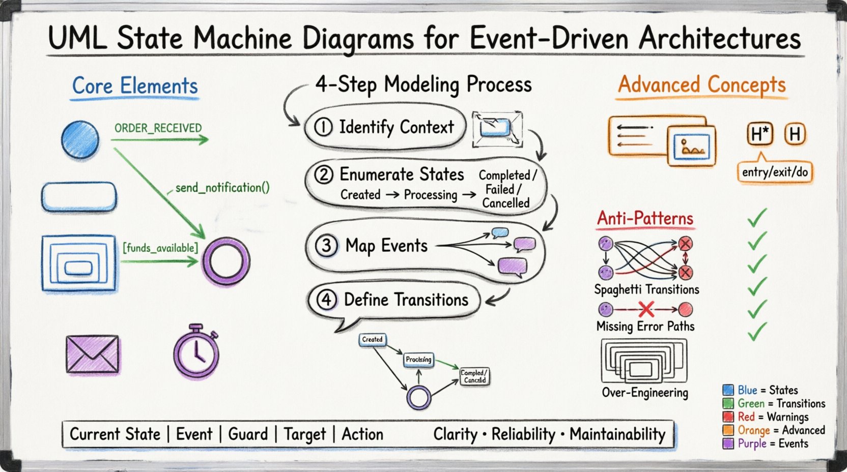
🧩 Core Elements of the Diagram
Before drawing, understand the building blocks. A state machine is not merely a flowchart; it is a finite state machine (FSM) representation.
1. States
A state represents a condition during which the system satisfies a specific requirement. In EDA, this often correlates with the status of a business process or the readiness of a service.
- Initial State: The starting point. Represented by a filled circle.
- Final State: The termination point. Represented by a double-filled circle.
- Simple State: A basic condition with no internal structure.
- Composite State: A state containing nested states. This is crucial for managing complexity.
- Orthogonal State: Multiple sub-states that run concurrently.
2. Transitions
A transition is the arrow connecting two states. It signifies the movement triggered by an event.
- Trigger Event: The signal that initiates the change (e.g.,
ORDER_RECEIVED). - Guard Condition: A boolean expression that must be true for the transition to occur (e.g.,
[funds_available]). - Action: Code executed during the transition (e.g.,
send_notification()).
3. Events
In EDA, events are the heartbeat of the system. They are asynchronous signals that do not block execution.
- Synchronous Events: Direct method calls.
- Asynchronous Events: Messages arriving from a queue or topic.
- Timers: Scheduled actions that trigger state changes after a duration.
🔄 Step-by-Step Modeling Process
Constructing a diagram requires a systematic approach. Do not begin with the drawing tool; begin with the logic.
Step 1: Identify the Context
Define the scope. Are you modeling a single microservice, a business process, or a specific entity like an Order?
- Keep the scope narrow. One diagram per entity is a common pattern.
- Define the boundaries. What is outside the state machine?
Step 2: Enumerate the States
List every possible status the entity can hold. Avoid creating states that are merely transient. If a state exists only for a split second, it might be an action, not a state.
- Created: The entity exists but is not active.
- Processing: Work is currently being done.
- Completed: The work is done successfully.
- Failed: The work did not succeed.
- Cancelled: The process was stopped before completion.
Step 3: Map the Events
For each state, list the events that can occur. What can the external system do?
- Did the user submit the order?
- Did the payment service respond?
- Did a timeout occur?
Step 4: Define the Transitions
Draw the arrows. Connect the states using the events identified in Step 3. Ensure every state has a path to the final state unless it is a long-running service.
📝 Advanced Concepts for Complex Systems
Simple diagrams are easy to read. Complex systems require advanced features to remain readable.
Composite States
When a state contains many sub-states, use a composite state (a rounded rectangle with internal states). This reduces visual clutter.
- Use this for states like
Processingthat have sub-steps likeValidating,Calculating, andRecording. - Ensure the composite state has a clear entry and exit point.
History States
When a composite state is exited and re-entered, where should the system resume?
- Deep History: Returns to the last active sub-state.
- Shallow History: Returns to the default initial sub-state.
This is vital in EDA where interruptions are common. If a service restarts, you do not want to restart the whole process from the beginning.
Entry, Exit, and Do Actions
Actions within a state can be categorized by when they occur.
- Entry (/): Runs once when entering the state.
- Exit (/): Runs once when leaving the state.
- Do (/): Runs continuously while in the state (useful for timers or polling).
🧱 Structuring Information with Tables
Text can be ambiguous. Tables provide a clear reference for state logic.
State Transition Table
Use a table to document the logic for developers who prefer reading data over graphics.
| Current State | Event | Guard Condition | Target State | Action |
|---|---|---|---|---|
| Created | Start_Process | – | Processing | log_init() |
| Processing | Payment_Received | [amount_valid] | Completed | commit_order() |
| Processing | Payment_Failed | – | Failed | notify_user() |
| Processing | Timeout | – | Failed | rollback() |
🚦 Handling Asynchronous Events
Event-Driven Architectures introduce timing issues. Messages may arrive out of order, or events may be lost.
Queuing Events
A state machine must handle events that arrive while processing another action. The diagram should imply a queue mechanism.
- Ensure the model accounts for event buffering.
- Document how concurrent events are prioritized.
Reentrancy
Can an event occur while the system is already in the target state of a previous transition?
- If yes, define if the action runs again or is ignored.
- This is critical for idempotency in distributed systems.
⚠️ Common Anti-Patterns
Avoid these mistakes to maintain the integrity of your model.
- Spaghetti Transitions: Too many crossing arrows make the diagram unreadable. Use composite states to group logic.
- Implicit Transitions: Never assume a transition happens without an event. Explicitly draw every path.
- Missing Error Paths: Always model failure states. A system that only works when everything is perfect is not robust.
- Over-Engineering: Do not model states that will never be reached. Keep the diagram focused on the current and near-future requirements.
✅ Validation and Maintenance
A diagram is a living document. It must evolve with the code.
Code-Model Alignment
The implementation should match the diagram. Use static analysis or linting tools to ensure the code adheres to the state definitions.
- Check that no state is skipped.
- Verify that guard conditions in code match the diagram.
Versioning
When the architecture changes, update the diagram immediately.
- Use version control for the diagram files.
- Document the change log for state modifications.
🔗 Integrating with Documentation
The diagram should not exist in isolation. It must be part of the broader system documentation.
- Sequence Diagrams: Use state machines for internal logic and sequence diagrams for external interaction.
- API Docs: Reference the state transitions in API documentation to explain valid request states.
- Runbooks: Include the state chart in troubleshooting guides to help operators understand system status.
🛡️ Security Considerations
State machines can be exploited if not secured properly.
- State Validation: Ensure the client cannot force a transition by manipulating state IDs.
- Event Integrity: Verify that events are signed and authenticated before processing.
- Access Control: Define which roles can trigger specific events.
📈 Performance Implications
The complexity of the state machine impacts performance.
- Lookup Speed: Avoid using large arrays or complex logic to determine the next state.
- Memory Usage: Store state data efficiently. Avoid keeping large objects in memory while in a waiting state.
- Concurrency: If using orthogonal regions, ensure thread safety when multiple regions update simultaneously.
📚 Summary of Best Practices
Follow this checklist to ensure high-quality diagrams.
- ✅ Use composite states for nested logic.
- ✅ Define clear entry and exit actions.
- ✅ Model error and timeout scenarios explicitly.
- ✅ Keep state names descriptive and consistent.
- ✅ Validate the diagram against actual code.
- ✅ Use tables for complex transition logic.
- ✅ Review the diagram during code reviews.
🎯 Final Thoughts
Building effective UML state machine diagrams for event-driven architectures is a discipline. It requires understanding the flow of data and the constraints of the system. By adhering to these principles, you create models that are not just documentation, but tools for development and maintenance. The goal is clarity, reliability, and maintainability. Stick to the fundamentals, avoid unnecessary complexity, and keep the diagram aligned with the code.
Remember, a state machine is a contract between the system and its environment. Honor that contract in every line of code and every arrow on the page. This ensures the system behaves predictably, even in the face of asynchronous chaos.