


Complex software systems require more than just code. They require a blueprint. A vision that stakeholders can understand and developers can execute. Senior architects face a critical choice when designing these systems: strict standardization or rapid iteration. This decision shapes the documentation strategy, the communication flow, and the long-term maintainability of the project.
The debate between Unified Modeling Language (UML) and Agile notation is not merely about tools. It is about the underlying philosophy of how information is captured and shared. One path offers precision and formal semantics. The other offers velocity and collaboration. Understanding the trade-offs is essential for making the right call in any given context.
The Architecture Documentation Dilemma 🤔
Why do we document at all? The answer lies in risk reduction and knowledge transfer. In large-scale projects, knowledge often lives in the heads of a few senior engineers. When those individuals move, the system becomes fragile. Diagrams serve as an external memory.
However, documentation comes with a cost. Time spent drawing diagrams is time not spent writing code. The value of documentation must exceed the cost of creating it. Senior architects must evaluate the return on investment for every diagram produced.
- Communication: Diagrams bridge the gap between business stakeholders and technical teams.
- Validation: Visual models help identify logical errors before implementation begins.
- Onboarding: New team members can understand the system architecture faster.
- Maintenance: Legacy systems require clear maps to navigate refactoring safely.
The challenge is selecting the right visual language. Using a heavy formalism for a simple feature adds unnecessary friction. Using a loose sketch for a critical financial transaction might introduce ambiguity.
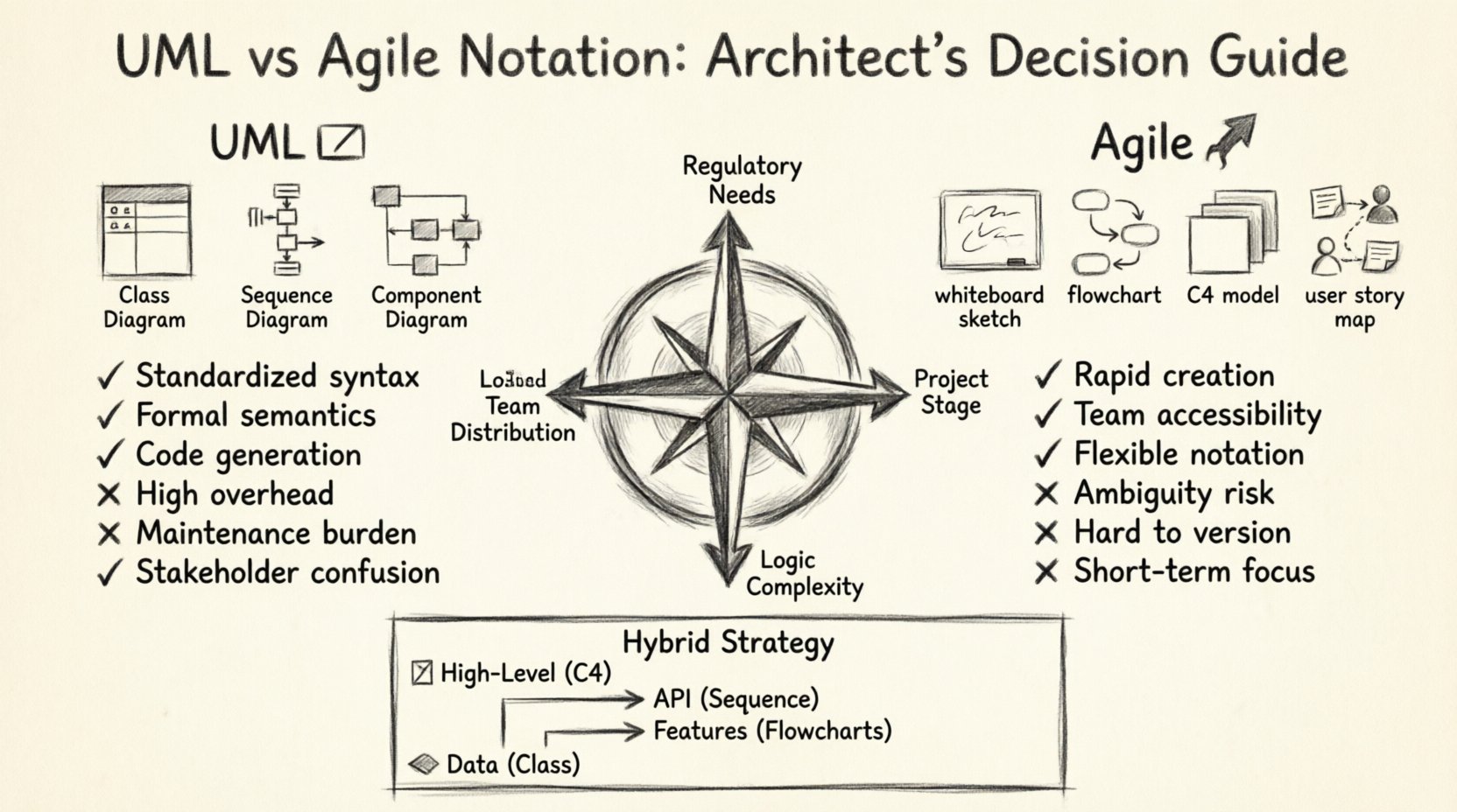
Deep Dive: Unified Modeling Language (UML) 📐
UML has been the industry standard for decades. It was designed to provide a common language for software engineering. The Object Management Group maintains the specification, ensuring consistency across different tools and teams.
UML is comprehensive. It covers structure, behavior, and interaction. It forces the architect to think about the system in a rigorous way. This rigor is its greatest strength and its primary weakness.
Key Diagram Types in UML
There are fourteen types of diagrams in the UML specification. Senior architects typically rely on a subset of these for daily work.
- Class Diagrams: These show the static structure of the system. They define classes, attributes, methods, and relationships like inheritance and association. They are crucial for database schema design and object-oriented architecture.
- Sequence Diagrams: These illustrate interactions between objects over time. They are excellent for defining API contracts and understanding request-response flows.
- Component Diagrams: These provide a high-level view of the system. They show how major subsystems interact and depend on one another.
- State Machine Diagrams: These define the lifecycle of an object. They are vital for systems with complex business logic, such as order processing or workflow engines.
- Deployment Diagrams: These map the software to the hardware infrastructure. They show servers, networks, and storage nodes.
Advantages of UML
- Standardization: Every engineer knows what a diamond or an arrow means. This reduces cognitive load during code reviews.
- Tooling: Many tools can generate code skeletons from UML class diagrams. They can also reverse-engineer existing codebases.
- Formalism: The syntax is strict. This eliminates ambiguity in technical specifications.
- Contract Enforcement: UML diagrams can serve as legal contracts between teams working on different modules.
Disadvantages of UML
- Overhead: Creating a detailed UML diagram takes significant time. It requires training and practice.
- Maintenance: Diagrams tend to rot. If code changes but the diagram does not, the documentation becomes a liability.
- Stakeholder Alienation: Business analysts and product owners often find UML syntax confusing and inaccessible.
- Complexity: Large systems can result in diagrams so large they are unreadable. They become wall charts rather than working tools.
The Agile Notation Alternative 🏃
Agile notation is less about standardization and more about communication. It emerged alongside the Agile Manifesto, prioritizing individuals and interactions over processes and tools.
This approach favors speed and clarity over formal precision. It is often associated with whiteboarding sessions, sticky notes, and simple flowcharts. The goal is to capture the essence of the idea quickly so the team can start building.
Common Techniques in Agile Notation
While not standardized like UML, several patterns are common in modern agile teams.
- C4 Model Concepts: This focuses on Context, Containers, Components, and Code. It provides a hierarchy of abstraction that scales from the big picture to the details.
- Whiteboard Sketches: Rough drawings used during planning meetings. They are discarded once the concept is understood.
- Flowcharts: Simple boxes and arrows showing decision points and paths. They are easier to read than sequence diagrams.
- User Story Maps: Visualizing the user journey and the features needed to support it. This aligns technical work with user value.
Advantages of Agile Notation
- Speed: You can draw a diagram in minutes. This fits well with sprint cycles.
- Accessibility: Anyone can understand a simple box-and-arrow diagram. It invites collaboration from non-technical roles.
- Flexibility: There are no rigid rules. You can adapt the notation to fit the specific problem.
- Focus on Flow: Agile diagrams often prioritize the user journey over the internal data structure.
Disadvantages of Agile Notation
- Ambiguity: Without standard symbols, meaning can be lost. What one person draws as a database, another might see as an API.
- Scalability: Large systems require many diagrams. Keeping them consistent across a large document is difficult.
- Version Control: Sketches are hard to track in version control systems compared to code or structured diagrams.
- Long-term Reference: Informal notes are often lost when a project ends or a team restructures.
Comparative Analysis Table 📊
To make a clear decision, it helps to compare the two approaches across key criteria.
| Feature | UML | Agile Notation |
|---|---|---|
| Precision | High. Strict syntax and semantics. | Medium. Focus on intent over detail. |
| Creation Speed | Slow. Requires formal modeling. | Fast. Quick sketches and flows. |
| Maintenance Cost | High. Synchronization with code is hard. | Low. Easy to update or discard. |
| Audience | Technical teams, contractors. | Product owners, developers, QA. |
| Tooling | Specialized modeling tools. | Whiteboards, digital boards, simple editors. |
| Best For | Complex state logic, regulated systems. | Rapid prototyping, MVP, small teams. |
Decision Framework for Senior Architects 🧠
Choosing between these notations is not binary. It depends on the context. Senior architects should evaluate the project environment before committing to a documentation strategy.
1. Regulatory and Compliance Requirements
Certain industries demand rigorous documentation. Healthcare, finance, and aerospace often require traceability. In these cases, UML is often the safer choice. It provides the audit trail needed for compliance.
If you are building a banking core system, you need to prove how data flows. A sequence diagram that maps every transaction step is better than a sketch.
2. Team Geography and Maturity
Remote teams benefit from UML. When people are not in the same room, ambiguity is costly. Standardized symbols ensure that a developer in one country understands the design intent of a lead in another.
Co-located teams can rely on Agile notation. If you can walk over to a desk and explain a diagram verbally, you do not need it to be perfectly precise on paper.
3. System Lifecycle Stage
Early stages favor Agile notation. You are exploring ideas. You do not know the final shape of the system. Sketching allows you to fail fast and pivot.
Late stages favor UML. As the system stabilizes, you need to document the agreed-upon architecture to prevent regression. This is when you formalize the design.
4. Complexity of Logic
Simple CRUD applications do not need complex state machines. A simple flowchart is sufficient. However, if your system involves complex workflows, such as a booking engine or a trading platform, UML state diagrams are necessary to capture edge cases.
Integrating Both Approaches 🔄
The most effective strategy is often a hybrid approach. Senior architects should not force a single standard across the entire organization. They should allow the documentation style to match the task.
- High-Level Design: Use C4-style diagrams or simplified UML component diagrams. These give the big picture without overwhelming detail.
- API Contracts: Use Sequence Diagrams or Swagger/OpenAPI definitions. These ensure data exchange is clear.
- Feature Flows: Use Agile notation or user story maps. These keep the focus on user value.
- Data Models: Use Class Diagrams. These are the foundation of the database schema.
This tiered approach ensures that the documentation is useful without being burdensome. It respects the time of the team while maintaining necessary rigor.
Pitfalls to Avoid 🚫
Even with a good strategy, teams can fall into traps. Awareness of these common mistakes helps maintain a healthy documentation culture.
1. Diagrams as Artifacts
Creating diagrams just to check a box is a waste of resources. Every diagram must serve a purpose. If it does not help someone build or understand the system, do not create it.
2. Stale Documentation
A diagram that does not match the code is worse than no diagram. It creates a false sense of security. Teams should integrate diagram updates into the definition of done for code changes.
3. Audience Mismatch
Showing a complex class diagram to a product manager is unhelpful. Showing a simple flowchart to a database engineer is insufficient. Tailor the notation to the consumer.
4. Over-Engineering Simple Flows
Do not use UML to model a simple email notification. A text description or a single line in a story is enough. Reserve formal modeling for complex interactions.
5. Ignoring the Code
Code is the ultimate source of truth. Diagrams are representations. If there is a conflict, the code wins. However, the code should ideally reflect the diagram to ensure the architecture is being followed.
Final Considerations on Technical Debt 📉
Documentation is a form of technical debt. It is an investment that must be paid back through better understanding and reduced errors. If the cost of maintaining diagrams exceeds the benefit, the debt is too high.
Senior architects must champion a culture where diagrams are living documents. They should be treated with the same care as code. Review them during design discussions. Update them during refactoring.
The choice between UML and Agile notation is not about which is better. It is about which fits the constraints of your project. Some projects need the rigor of UML. Others need the speed of Agile. The best architects know when to use which tool.
By understanding the strengths and weaknesses of each notation, you can build systems that are both robust and adaptable. Documentation should support the team, not hinder it. Choose the path that enables your team to deliver value with confidence.
Remember, the goal is not to produce perfect diagrams. The goal is to build reliable software. Use the visual language that gets you there most efficiently.