

Unified Modeling Language (UML) activity diagrams are powerful tools for visualizing the dynamic aspects of a system. They represent workflows, logic, and decision points in a graphical format that is often easier to digest than dense textual requirements. However, a diagram that is technically correct can still fail to communicate effectively. Many teams create activity diagrams that are overly complex, inconsistent, or ambiguous, leading to significant confusion among stakeholders.
This guide explores the frequent pitfalls in modeling activity flows and offers concrete strategies to create clear, actionable diagrams. We will examine how to structure logic, handle concurrency, and maintain consistency without relying on specific software tools. By understanding these common errors, you can ensure your process models serve their primary purpose: bridging the gap between technical implementation and business understanding.
Understanding the Purpose of Activity Diagrams 🎯
Before diving into mistakes, it is essential to clarify what an activity diagram is meant to achieve. It is not merely a flowchart. It captures the flow of control and the flow of data through a system. It should answer questions like:
- What happens first, second, and third?
- Where do decisions occur?
- How do parallel processes interact?
- When does the process end?
When these questions are not answered clearly, the diagram becomes noise rather than signal. Stakeholders, who may include business analysts, project managers, and developers, need to trace the path from start to finish without getting lost in notation errors or logical gaps.
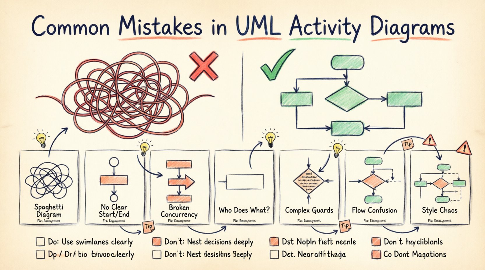
Top 7 Common Mistakes in UML Activity Modeling 🚫
The following sections detail the most prevalent errors found in activity diagrams. Recognizing these patterns is the first step toward correction.
1. The Spaghetti Diagram 🍝
One of the most damaging errors is creating a diagram with too many crossed lines and overlapping paths. This happens when modelers try to fit every possible scenario into a single view without breaking the process down.
- Visual Clutter: When lines cross excessively, tracing a specific path becomes a game of hide-and-seek.
- Loss of Context: Complex diagrams force the reader to hold too much information in their working memory.
- Maintainability: A tangled diagram is difficult to update when requirements change.
Fix: Use subactivities. Break large processes into smaller, manageable activities. Link them using call behaviors or object flows. This modular approach keeps the high-level view clean while preserving detail in nested diagrams.
2. Missing Initial and Final Nodes ⏹️
A valid activity diagram must have a clear beginning and a clear end. Omitting the initial node (a filled black circle) or the final node (a filled black circle within a border) creates ambiguity about where the process starts and stops.
- Start Point: Without an initial node, it is unclear what triggers the activity.
- End Point: Without a final node, it is unclear if the process completes or if it waits indefinitely.
- Multiple Ends: While multiple final nodes are allowed, they must represent distinct termination states (e.g., Success vs. Failure).
Fix: Always explicitly define the entry point. Ensure every path eventually leads to a final node, or explicitly define an exception path that terminates the flow.
3. Misusing Fork and Join Nodes ⚖️
Fork and join nodes are used to model concurrency. A fork splits a single flow into multiple parallel flows. A join merges those parallel flows back into a single flow. Errors here often lead to logical deadlocks or lost data.
- Unbalanced Forks: Splitting into paths that never rejoin without a join node.
- Missing Join: Failing to synchronize parallel threads, which might cause the system to proceed before all tasks are complete.
- Wrong Bar Style: Confusing the synchronization bar (join) with the control bar (fork). In standard UML, both are horizontal bars, but context implies their function.
Fix: Ensure every fork has a corresponding join unless the intent is specifically for parallel threads to terminate independently. Use guard conditions on the incoming edges of join nodes if synchronization is conditional.
4. Ignoring Swimlanes (Partitioning) 🏊
Swimlanes define who or what is responsible for an activity. They can represent organizational roles, departments, or system components. Omitting swimlanes makes it impossible to distinguish between human tasks and system actions.
- Ambiguity: Who performs this step? Is it an automated script or a human approval?
- Handoff Gaps: Without partitions, the transfer of control between actors is invisible.
- Responsibility Confusion: Stakeholders cannot see who owns the bottlenecks.
Fix: Use partitions to group activities by actor or system component. This visualizes the handoffs and clarifies accountability across the process.
5. Overloading Guard Conditions ⚙️
Guard conditions are boolean expressions on edges that determine if a path is taken. A common mistake is writing complex logic directly on the diagram edge.
- Readability: Long expressions like
(user.role == 'admin' AND user.status == 'active')clutter the diagram. - Maintainability: If the logic changes, the diagram must be edited in multiple places.
- Clarity: Stakeholders often cannot parse complex boolean logic quickly.
Fix: Keep guard conditions simple. If the logic is complex, move it to a separate specification or a decision node description. Use labels like Is Valid? or Check Permission instead of full code snippets.
6. Mixing Data Flow with Control Flow 🔄
UML activity diagrams primarily model control flow (the order of execution). However, they can also model object flow (data passing between actions). Mixing these without clear distinction confuses the reader.
- Arrow Confusion: Solid arrows usually mean control flow. Open arrows or dashed lines often indicate object flow.
- Logic Errors: If an object is required for an action but no object flow is shown, the dependency is hidden.
- State Confusion: Confusing the state of an object with the state of the process flow.
Fix: Use object flows explicitly when data is needed. If the data is implied by the action name, do not clutter the diagram with object flows. Be consistent with arrow styles.
7. Inconsistent Notation and Symbols 🎨
Using non-standard symbols or varying styles for the same elements creates cognitive friction. If one decision diamond is a rhombus and another is a circle, the reader must stop to relearn the meaning.
- Style Variance: Different shapes for the same element type.
- Label Inconsistency: Sometimes using
Yes/No, sometimesTrue/False, sometimesPass/Fail. - Font Issues: Changing font sizes or types for emphasis rather than structure.
Fix: Establish a notation standard for the team. Define exactly what shapes mean and stick to them. Use consistent labeling conventions for decision outcomes.
Impact on Stakeholder Communication 🗣️
When these mistakes occur, the impact extends beyond technical debt. It affects the business relationship.
- Loss of Trust: If stakeholders cannot understand the process flow, they lose faith in the modeling effort.
- Requirement Gaps: Ambiguity leads to missed requirements during implementation.
- Rework: Developers build based on a flawed mental model, requiring expensive corrections later.
- Delayed Sign-off: Business approval is delayed because the diagram is too difficult to review.
Clarity is not just about aesthetics; it is about reducing risk. A clear diagram validates the business logic before a single line of code is written.
Do’s and Don’ts Checklist ✅❌
The table below summarizes the key behaviors for creating effective activity diagrams.
| Aspect | Do | Don’t |
|---|---|---|
| Complexity | Break processes into sub-activities. | Fit every scenario into one view. |
| Start/End | Define clear initial and final nodes. | Leave the start or end undefined. |
| Concurrency | Use fork/join pairs correctly. | Split flows without rejoining them. |
| Responsibility | Use swimlanes to show actors. | Hide who performs the action. |
| Logic | Keep guard conditions simple. | Embed complex code on edges. |
| Consistency | Use standard UML notation. | Invent custom shapes or symbols. |
Structuring for Clarity: Best Practices 📝
Beyond avoiding mistakes, there are proactive steps to ensure your diagrams serve their purpose.
1. Define Scope Early
Before drawing, define what is in scope. Does the diagram cover the entire system or just a specific module? Mark boundaries clearly. If a process involves external systems, use a boundary box or a specific activity to indicate the interface.
2. Use Object Flows Judiciously
Object flows add significant value but can also clutter. Only show data flows that are critical to the logic. If an action simply transforms an object that is already present, you may not need to draw the input flow explicitly.
3. Prioritize the Happy Path
Focus on the primary success flow first. Add exception handling and error paths only after the main flow is stable. This ensures the core process is understood before dealing with edge cases.
4. Review with Business Users
Technical correctness is not enough. The diagram must be readable by the business side. Conduct a walkthrough with a non-technical stakeholder. If they hesitate or ask clarifying questions, simplify the diagram further.
Advanced Considerations for Complex Flows 🔧
For enterprise-level systems, activity diagrams often require handling state, constraints, and timing.
Handling Time and Constraints
Some processes are time-dependent. You can annotate activities with constraints like [timeout: 5min]. However, do not overuse this. Time constraints are often better handled in sequence diagrams or state machine diagrams.
Exception Handling
Every process should anticipate failure. Use exception handlers to show how the system recovers from errors. This might involve looping back to a previous step or triggering a notification activity.
Refinement and Iteration
An activity diagram is rarely finished in one pass. It evolves as understanding deepens. Treat the diagram as a living document. When requirements change, update the diagram immediately to maintain the source of truth.
Final Thoughts on Modeling Quality 🏁
Creating UML activity diagrams is an exercise in abstraction. The goal is not to document every detail but to capture the essential logic that drives the system. By avoiding common mistakes like spaghetti layouts, missing nodes, and confusing notation, you ensure that your models are assets rather than liabilities.
Focus on the audience. If the diagram helps the business analyst validate the requirement, the developer implement the logic, and the tester verify the behavior, then the modeling effort has succeeded. Clarity, consistency, and simplicity are the hallmarks of effective process modeling. Keep your diagrams clean, your logic sound, and your stakeholders informed.