

Designing software for long-running processes presents unique challenges. Unlike short-lived transactions, these systems must maintain state across minutes, hours, or even days. They must handle interruptions, external events, and recovery scenarios without losing context. This is where the Unified Modeling Language (UML) State Machine Diagram becomes an essential tool. It provides a rigorous method for modeling the lifecycle of an object or system based on events and conditions.
Many teams struggle with spaghetti code when managing complex workflows. They rely on simple if-else logic that becomes unmaintainable as the number of states grows. A formal state machine approach forces clarity. It separates the control logic from the data logic. This guide explores the mechanics of UML state machines, specifically tailored for managing complexity in long-running processes.
🏗️ Understanding the Foundation of State Machines
A state machine is a model of behavior for a single object. It defines how that object reacts to events. The object exists in exactly one state at a time. Transitions occur when specific conditions are met. This is distinct from a flowchart, which shows a sequence of actions without necessarily tracking the internal condition of the system.
- State: A condition or situation during the life of an object during which it satisfies some condition, performs some activity, or waits for some event.
- Transition: A relationship between two states indicating that objects in the first state will move to the second state when a specific event occurs and a condition is met.
- Event: A significant occurrence in time and space that may trigger a transition.
- Action: A specification of the work that is performed during a transition or while an object is in a state.
In the context of long-running processes, the “object” is often the process instance itself. It must remember where it left off. If a server restarts or a network connection drops, the process needs to resume from the correct state. This requirement for persistence is the primary driver for using state machine diagrams in this domain.
🔍 Core Elements and Anatomy
To build a robust diagram, one must understand the building blocks. Each element serves a specific purpose in defining behavior.
1. Initial State
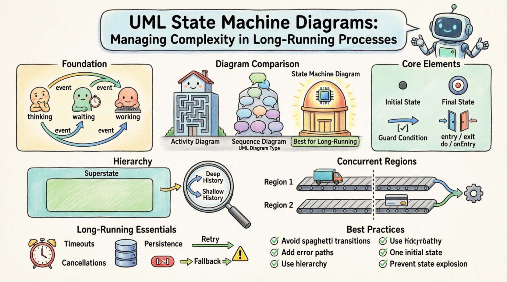
The journey begins here. The initial state is represented by a solid black circle. It marks the entry point for the process. A process does not exist in a valid state until it has moved past the initial state. This ensures that the system cannot start in a valid but undefined condition.
2. Final State
Represented by a circle with a dot inside, this marks the termination of the process. A process can have multiple final states. For example, a loan application process might end in “Approved” or “Rejected”. Both are valid ends, but they represent different outcomes.
3. Transitions
Transitions are the lines connecting states. They are labeled with an event. The label can include a guard condition in square brackets. For instance, submit / [validate=true] means the event submit occurs, but the transition only happens if validate is true. This guards against invalid state changes.
4. Entry and Exit Actions
States are not passive containers. They execute logic. When entering a state, an entry action runs. When exiting a state, an exit action runs. This is crucial for long-running processes.
- Entry Action: Initialize variables, start timers, or send notifications when the process enters a specific phase.
- Exit Action: Clean up resources, log the completion of a phase, or prepare data for the next state.
- Do Action: This activity continues as long as the object remains in the state. It is useful for processes that need to run continuously while waiting for a timeout.
📊 Comparing Diagram Types
Choosing the right diagram is vital. UML offers several behavioral diagrams. Using the wrong one leads to confusion.
| Diagram Type | Primary Focus | Best Use Case | Limitation |
|---|---|---|---|
| Activity Diagram | Workflow and Data Flow | Step-by-step business processes | Does not model internal state persistence well |
| Sequence Diagram | Interaction Over Time | API calls and message passing | Hard to show the lifecycle of a single object |
| State Machine Diagram | State and Events | Complex lifecycles with interruptions | Can become complex if not hierarchical |
For long-running processes, the State Machine Diagram is superior because it explicitly models the memory of the system. An activity diagram shows what happens next, but a state machine shows what the system is while it waits.
🏛️ Managing Complexity with Hierarchy
As processes grow, a flat list of states becomes unreadable. UML addresses this with hierarchical states. A state can contain substates. This allows you to group related behaviors without cluttering the main diagram.
1. Superstates
A superstate is a state that contains other states. Transitions to or from the superstate affect all substates. This is useful for common logic shared across multiple phases.
2. Deep History vs. Shallow History
When a state is exited and then re-entered via a history transition, the system needs to know where it was. This is the concept of History States.
- Shallow History: Returns to the most recently active top-level substate.
- Deep History: Returns to the most recently active nested substate. This is critical for complex processes where a user might be several layers deep in a workflow.
Consider a payment processing system. If the user leaves the “Payment Details” state and returns, a deep history state ensures they return to the specific card type they were editing, not just the generic “Payment Details” state.
🔄 Concurrent Regions and Orthogonality
Long-running processes often involve independent activities happening at the same time. A single linear state machine cannot model this well. UML supports orthogonal regions. These are separate state machines within the same composite state.
Imagine an order processing system. While the system waits for shipping confirmation (Region 1), it might also be waiting for payment verification (Region 2). These regions operate independently. An event in Region 1 does not block Region 2. This parallelism is modeled using a composite state with multiple subregions separated by a dashed line.
- Independence: Events in one region do not trigger transitions in another.
- Synchronization: A composite state is only active when all subregions are active.
- Termination: The composite state terminates only when all subregions terminate.
This structure prevents the “comb of death” in diagramming, where every state in one region needs a transition to every state in another. Instead, they run in parallel until a join condition is met.
⏳ Long-Running Process Specifics
Designing for processes that run for a long time introduces specific constraints. The diagram must account for time, persistence, and external interruptions.
1. Timeouts and Timers
Processes often have deadlines. A state machine can model this using timer events. A transition might be triggered by timeout or timer(expire). This allows the system to move to an error state or a reminder state if no action occurs within a set period.
2. Persistence and Serialization
In a distributed system, a state machine instance might be serialized to a database. The diagram defines the schema of the state. When the process is paused (e.g., waiting for a user response), the current state ID, entry actions, and history are saved. Upon resumption, the system reads the state ID and restores the context.
3. Handling Interruptions
External events can interrupt a process at any time. For example, a user might cancel an order while it is being processed. The state machine must define transitions for these interruptions from every relevant state. This is often handled via a “Cancel” event that is valid in multiple states, leading to a “Cancellation” substate.
4. Error Handling
Errors are not just transitions; they are states. A generic “Error” state is insufficient. Instead, model specific error states like “Network Timeout” or “Validation Failed”. This allows for different recovery strategies for different errors. Some errors can be retried automatically, while others require human intervention.
🛠️ Implementation Patterns
Translating the diagram into code requires a disciplined approach. The diagram is the source of truth; the code is the implementation.
1. Event-Driven Architecture
The core of a state machine is the event queue. Events are enqueued and processed sequentially. This prevents race conditions where two events arrive simultaneously and corrupt the state. The diagram dictates the order of processing. An event that is not valid in the current state is either discarded or logged as an unexpected event.
2. Guard Conditions
Guard conditions are boolean expressions that must evaluate to true for a transition to occur. They should be kept simple. Complex logic should be moved to the action layer. This keeps the diagram readable. For example, instead of [user.age > 18 && user.verified == true], use [isValidUser] and define the logic in the entry action of the state.
3. Action Semantics
Distinguish between actions that are synchronous and asynchronous. If a transition triggers an external API call, the state machine should wait for the response before considering the transition complete. This is often modeled as a “Wait” state. The process moves to a “Pending” state, waits for a callback event, and then transitions to the final state.
⚠️ Common Pitfalls and Best Practices
Even with a solid model, implementation errors occur. Here are common issues to avoid.
- Spaghetti Transitions: Avoid lines crossing over each other. Use hierarchy to group related states. If you have 50 states, you likely need substates.
- Missing Error Paths: Every transition should have a failure path. What happens if the API call fails? Define a transition to an error state.
- Overusing History: History states are powerful but confusing. Use them only when the substate structure is deep. Otherwise, explicit transitions are clearer.
- Ignoring Initial State: Ensure there is exactly one initial state. If there are multiple, the diagram is invalid. The system must know exactly how to start.
- State Explosion: If the number of states grows too large, consider splitting the diagram into multiple interacting machines. Do not try to model everything in one massive diagram.
📝 Summary of Considerations
Using UML State Machine Diagrams for long-running processes is about managing complexity through structure. It forces the designer to think about every possible condition the system might face. It separates the lifecycle from the business logic.
By utilizing hierarchical states, concurrent regions, and history states, you can create models that are both comprehensive and maintainable. The key is to treat the diagram as a contract. The code must adhere to the transitions and events defined in the visual model. This alignment reduces bugs and makes the system easier to debug.
When building complex systems, do not underestimate the value of a well-drawn diagram. It serves as documentation, a design tool, and a communication bridge between technical and non-technical stakeholders. It ensures that the logic for handling interruptions, timeouts, and recoveries is not an afterthought but a foundational element of the architecture.
Focus on clarity. Use the visual language of UML to express the temporal behavior of your system. When you master the structural aspects of state machines, you gain the ability to build systems that are resilient, predictable, and robust.