

In the landscape of software engineering, complexity is the constant variable. As systems grow from simple scripts into enterprise-grade applications, the architecture must evolve to maintain stability and readability. One of the most effective tools for visualizing this structure is the UML Package Diagram. This diagram type serves as a high-level map, allowing architects and developers to understand how components relate without getting lost in the minutiae of class-level details.
This guide explores the mechanics, design principles, and strategic applications of package diagrams. We will examine how to structure namespaces, manage dependencies, and maintain clarity within massive codebases. By adhering to standardized modeling practices, teams can reduce cognitive load and improve collaboration.
🏗️ What is a UML Package Diagram?
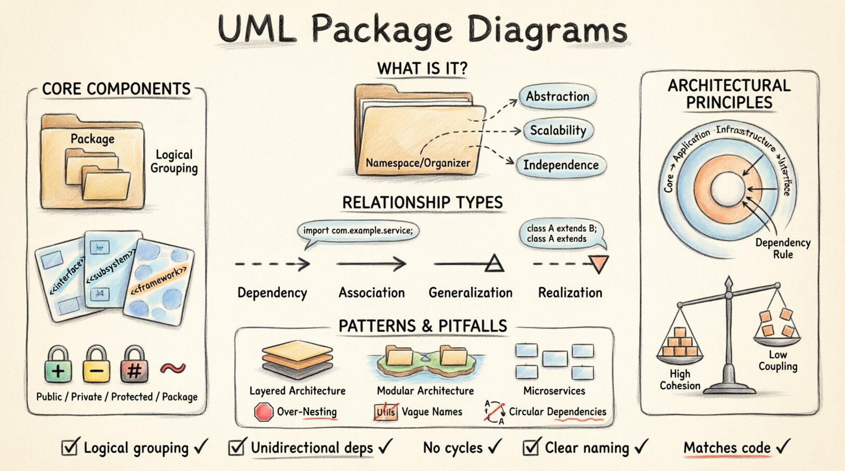
A UML Package Diagram is a structural diagram used in the Unified Modeling Language. It groups elements into packages to show the organization of system components. Unlike class diagrams that focus on individual objects and their attributes, package diagrams operate at a meta-level. They visualize the macro structure of the software.
Key characteristics include:
- Abstraction: They hide implementation details to focus on logical grouping.
- Scalability: They allow for nesting, enabling the representation of complex hierarchies.
- Independence: They can be created before code exists or after code is written to document the current state.
When managing a large codebase, understanding the boundary between modules is critical. Package diagrams provide the visual language necessary to define these boundaries clearly. They answer questions such as “Which module calls which?” and “Where does the business logic end and the data layer begin?”
🧩 Core Components and Anatomy
To utilize this diagramming technique effectively, one must understand the fundamental building blocks. Every package diagram consists of specific elements that define the system’s layout.
1. Packages
A package is a namespace that organizes a set of related elements. It is often represented as a folder icon with a tab. In the context of a codebase, a package typically corresponds to a directory or a module.
- Logical Grouping: Packages group classes, interfaces, or other packages.
- Naming: Names should be descriptive, often reflecting the domain (e.g.,
com.company.project.auth). - Nesting: Packages can contain other packages, creating a tree structure.
2. Stereotypes
Stereotypes extend the vocabulary of UML. They allow developers to categorize packages or elements with specific meanings. Common stereotypes in this context include:
- <<interface>>: Indicates a package containing primarily interface definitions.
- <<subsystem>>: Denotes a major component of the system.
- <<framework>>: Suggests a reusable architecture.
3. Visibility Modifiers
Visibility determines the accessibility of elements within a package. Standard modifiers apply:
- Public (+): Accessible by any other package.
- Private (-): Accessible only within the same package.
- Protected (#): Accessible within the package and child packages.
- Package (~): Accessible within the package and its sub-packages.
🔗 Understanding Relationships and Dependencies
The true power of a package diagram lies in the relationships between packages. These lines define the flow of control and data. Mismanaged relationships lead to tight coupling, making the system fragile. Correctly mapped relationships promote modularity.
There are four primary types of relationships used in this context:
- Dependency: A usage relationship where one element needs another to function.
- Association: A structural relationship where objects are connected.
- Generalization: Inheritance or implementation relationships.
- Realization: Often used for interfaces implemented by classes.
Dependency Management
Dependencies are the most critical aspect of package diagrams. A dependency implies that changes in one package may necessitate changes in another. Minimizing dependencies is a primary goal of architectural design.
Relationship Types Table
| Relationship Type | Symbol Description | Implication | Usage Scenario |
|---|---|---|---|
| Dependency | Dashed arrow with open arrowhead | One package uses another | Calling a method in another module |
| Association | Solid line | Structural link between packages | Shared data ownership |
| Generalization | Solid line with hollow triangle | Inheritance or specialization | Extending functionality |
| Realization | Dashed line with hollow triangle | Implementation of contract | Interface adherence |
🛡️ Architectural Principles for Clarity
Creating a diagram is only half the battle. Applying sound architectural principles ensures the diagram reflects a maintainable system. The following principles guide the organization of packages.
1. High Cohesion, Low Coupling
Cohesion refers to how closely related the responsibilities of a package are. Coupling refers to how much a package depends on others.
- High Cohesion: All classes in a package should serve a single purpose. For example, a
Paymentpackage should handle only payment logic, not user authentication. - Low Coupling: Packages should interact through well-defined interfaces. Direct access to internal data structures of other packages should be avoided.
2. The Dependency Rule
Dependencies should flow inward. Core business logic should not depend on external infrastructure (like databases or UI frameworks). Instead, infrastructure should depend on the core logic. This is often visualized as concentric circles in a package diagram.
3. Separation of Concerns
Each package should address a specific concern. Splitting a monolithic system into distinct areas prevents the “spaghetti code” effect. Common separations include:
- Domain Layer: Business rules and entities.
- Application Layer: Use cases and workflow.
- Infrastructure Layer: Database access, file systems, and external APIs.
- Interface Layer: User interface and presentation.
🧱 Common Architectural Patterns
Several proven patterns utilize package diagrams to define system boundaries. Selecting the right pattern depends on the project’s scale and requirements.
Layered Architecture
This is the most common structure. It organizes packages into layers, such as Presentation, Business Logic, and Data Access. Each layer interacts only with the one below it. This restricts the flow of information and prevents circular dependencies.
Modular Architecture
In this approach, the system is divided into interchangeable modules. Each module encapsulates a specific functionality. This is particularly useful for large teams working in parallel. A package diagram for this structure will show distinct islands of packages with minimal connections between them.
Microservices Boundaries
Even in distributed systems, package diagrams help define service boundaries. They clarify which logic belongs to which service. This prevents the “distributed monolith” anti-pattern, where services share too much internal state.
🔍 Managing Complexity and Visibility
As the number of packages grows, visibility becomes a management challenge. Developers need to know what is public and what is internal. Package diagrams help visualize these scopes.
Namespace Resolution
When a package imports another, the compiler or runtime must resolve the namespace. Clear naming conventions prevent ambiguity. For example, using fully qualified names in diagrams helps trace the exact path to a dependency.
Handling Cycles
Circular dependencies occur when Package A depends on Package B, and Package B depends on Package A. This creates a logical loop that is difficult to compile or maintain. Package diagrams make these cycles immediately visible.
- Identify: Look for closed loops of dependency arrows.
- Resolve: Extract the common logic into a third package that both original packages depend on.
- Refactor: Use dependency injection to break tight links.
Documentation Strategy
Diagrams should not be static artifacts. They must evolve with the code. A maintenance strategy should include:
- Version Control: Store diagrams alongside source code.
- Review Process: Update diagrams during code reviews.
- Generation: Consider tools that generate diagrams from code to ensure accuracy.
📉 Common Pitfalls to Avoid
Even experienced architects make mistakes. Recognizing these pitfalls early saves time during the design phase.
- Over-Nesting: Creating too many levels of packages makes navigation difficult. Aim for a depth of 3 to 4 levels maximum.
- Vague Names: Names like
UtilsorLibprovide no context. Use domain-specific names likeOrderProcessing. - Ignoring Interfaces: Showing only concrete classes in a diagram hides the abstraction layer. Always show the interfaces that packages implement.
- Mixing Layers: Placing UI logic inside the database package violates separation of concerns.
🔄 Maintenance and Evolution
A codebase is never finished. It evolves. The package diagram must reflect this evolution. When new features are added, new packages are created. When features are deprecated, packages are removed or merged.
Refactoring Triggers
Specific changes in the diagram indicate a need for refactoring:
- Explosive Growth: If one package contains significantly more elements than others, it is likely doing too much.
- Dense Connections: If a package has arrows connecting to almost every other package, it is too coupled.
- Orphaned Packages: Packages with no incoming dependencies that are not root nodes may be unnecessary.
Alignment with Code
There should be a direct mapping between the physical file structure and the logical package diagram. If the directory structure diverges from the model, confusion arises. Developers should use the package diagram as the source of truth for folder organization.
📝 Practical Checklist for Implementation
Before finalizing a design, review the following checklist to ensure robustness.
- ☐ Are all packages logically grouped by function?
- ☐ Are dependencies unidirectional where possible?
- ☐ Are circular dependencies eliminated?
- ☐ Are visibility modifiers correctly assigned?
- ☐ Is the naming convention consistent across all packages?
- ☐ Are stereotypes used to clarify package types?
- ☐ Is the diagram readable without excessive zooming?
- ☐ Does the diagram match the actual code structure?
🚀 Conclusion
Organizing a massive codebase requires discipline and clear visualization. The UML Package Diagram provides the necessary framework to achieve this. By defining boundaries, managing dependencies, and enforcing architectural principles, teams can build systems that are stable and scalable. The effort invested in designing these diagrams pays dividends in reduced technical debt and improved developer productivity.
Focus on clarity over complexity. A simple diagram that accurately reflects the system is far more valuable than a complex one that obscures the truth. Use these tools to guide your design, but remember that the code itself is the ultimate documentation. Regularly review and update your models to ensure they remain relevant as the project matures.