

In the complex landscape of modern software development, ensuring seamless interaction between components is paramount. When building multi-tier applications, the separation of concerns often introduces communication gaps. These gaps frequently manifest as UML collaboration issues. Understanding how to diagnose these communication failures requires a deep look into object lifelines and message passing. This guide provides a technical framework for identifying, analyzing, and resolving structural inconsistencies within Unified Modeling Language diagrams.
Multi-tier architectures rely on distinct layers—presentation, application logic, and data access. Each layer interacts through defined interfaces. When these interactions are not modeled accurately, the resulting UML diagrams fail to reflect reality. This leads to development errors, runtime exceptions, and architectural drift. The goal here is not just to draw diagrams, but to ensure they serve as a reliable contract between system parts.
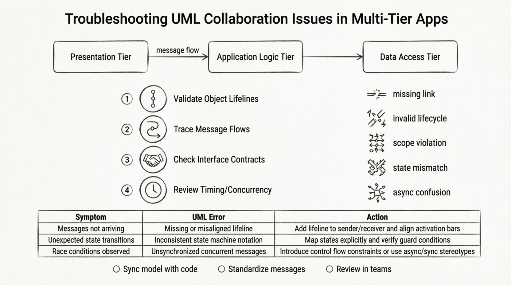
🏗️ Understanding Multi-Tier Architecture Context
Before troubleshooting, one must understand the environment. A multi-tier application divides functionality into distinct logical layers. Typically, this includes:
- Presentation Tier: The user interface where user inputs occur and results are displayed.
- Application (Logic) Tier: The core processing engine that handles business rules and workflow.
- Data Access Tier: The interface responsible for retrieving and storing information in databases or external services.
Collaboration diagrams in UML visualize how objects in these tiers interact. They map out the flow of messages between instances. When a message fails to traverse the intended path, it indicates a breakdown in the model. This breakdown often stems from ambiguity in class responsibilities or incorrect dependency mapping.
📊 Types of Collaboration Diagrams
UML provides several diagram types to model interactions. Identifying the correct type is the first step in troubleshooting. Different diagrams highlight different aspects of communication.
1. Sequence Diagrams
Sequence diagrams focus on time. They arrange objects horizontally and messages vertically. This layout is ideal for spotting timing issues, such as asynchronous calls or race conditions. If a message is sent before an object is fully initialized, the diagram will show a broken lifeline or an invalid activation bar.
2. Communication Diagrams
Communication diagrams (formerly Collaboration Diagrams) focus on structure. Objects are arranged based on their spatial relationships. Messages are numbered to show the sequence. This type helps identify circular dependencies or overly complex coupling between classes. If the numbering is inconsistent, the logical flow of data is compromised.
3. Interaction Overview Diagrams
These combine activity diagrams with interaction diagrams. They provide a high-level view of a complex process. Troubleshooting here involves checking the flow control nodes. If a path is missing or a loop condition is undefined, the overall system logic becomes opaque.
🚨 Common Communication Failures in Multi-Tier Apps
Diagnosing problems requires recognizing specific failure patterns. Below are the most frequent issues encountered when modeling multi-tier systems.
- Missing Message Links: A critical object in the logic tier receives a request but has no defined response path. This results in silent failures or null pointer exceptions in the actual code.
- Invalid Object Lifecycle: An object is used before it is created, or after it is destroyed. In UML, this violates the rules of object activation.
- Scope Violations: Messages cross boundaries without proper interface definitions. For example, the presentation tier directly accessing the data tier, bypassing the logic layer.
- State Mismatch: The state of an object in the diagram does not match its actual runtime state. This often happens when the model is not updated after code refactoring.
- Asynchronous Confusion: Modeling synchronous calls where asynchronous events occur, or vice versa. This affects how the system handles concurrency and blocking.
🔍 Diagnostic Workflow
Resolving these issues requires a systematic approach. Follow this workflow to isolate the root cause of collaboration breakdowns.
Step 1: Validate Object Lifelines
Check every object instance in the diagram. Ensure that every lifeline has a valid creation event and a termination event. If a lifeline starts without a creator, it implies a singleton that was not defined. If it ends prematurely, data may be lost. Verify that the activation bars align with the duration of the operation.
Step 2: Trace Message Flows
Select a critical path from the presentation tier to the data tier. Trace every message arrow. Ensure that every message has a return arrow or an explicit acknowledgement. If a message flows out but never returns, the model assumes a fire-and-forget pattern that might not exist in the code. Check for loops. Infinite loops in diagrams indicate logic errors in the underlying algorithms.
Step 3: Check Interface Contracts
Verify that the receiving object implements the interface defined by the sender. If the sender expects a specific method signature, the receiver must provide it. In multi-tier systems, this often involves checking API definitions. If the diagram shows a method call that is abstract in the receiver, the collaboration is invalid.
Step 4: Review Timing and Concurrency
For high-traffic applications, timing matters. Look for parallel messages. In a sequence diagram, parallel messages are drawn on separate horizontal lanes. If these messages access shared resources without synchronization markers, race conditions are likely. Ensure that wait blocks are modeled correctly where blocking is required.
📋 Troubleshooting Reference Table
Use this table to quickly map symptoms to potential model errors.
| Symptom | Potential UML Error | Diagnostic Action |
|---|---|---|
| System crashes on specific input | Missing error handling path in diagram | Trace exception handling branches |
| Slow response times | Unnecessary synchronous blocking calls | Identify blocking waits and convert to async |
| Null reference errors | Object instantiated without initialization | Check constructor calls in sequence |
| Data inconsistency | Multiple writes to same object without locks | Review concurrent access markers |
| Layer bypass detected | Direct link between non-adjacent tiers | Insert intermediate logic objects |
| Unresolved dependencies | Missing import or dependency declarations | Verify package and class imports |
🔄 Maintaining Model Synchronization
One of the primary causes of collaboration issues is the divergence between the model and the code. As the application evolves, the UML diagrams often become stale. This drift creates false positives during troubleshooting. To prevent this, adopt a maintenance strategy.
- Iterative Updates: Update diagrams in small increments alongside code changes. Do not attempt to document the entire system at once. This keeps the model relevant.
- Code Generation: Where possible, use reverse engineering features in modeling tools to regenerate diagrams from existing code. This ensures the visual representation matches the actual implementation.
- Peer Reviews: Include diagram reviews in the standard code review process. Architects should verify that the interaction logic holds up against the new code.
- Version Control: Treat UML files as code. Commit them to the repository. This allows you to track changes over time and revert if a model update introduces confusion.
🧩 Refactoring Collaboration Patterns
Sometimes the issue is not a mistake, but a design smell. If collaboration diagrams are overly complex, the design itself may need refactoring. Complex diagrams are hard to debug. Simplify the interaction flow.
Reduce Coupling
High coupling creates fragile systems. If Object A knows too much about Object B, changes in B break A. Use interface segregation to reduce the number of messages required between layers. Introduce a Facade object to simplify the interaction with complex subsystems.
Clarify Responsibilities
Ensure each object has a single, clear responsibility. If an object handles both data retrieval and business logic, the diagram becomes cluttered. Split the object into a Service class and a Repository class. This separation makes the message flow clearer and easier to troubleshoot.
Standardize Message Names
Use consistent naming conventions for messages. If one part of the diagram calls a method getUser and another calls fetchUser, confusion arises. Standardize these names to reflect the domain language. This improves readability and reduces the cognitive load during diagnosis.
🤝 Team Communication and Alignment
UML is a communication tool, not just a technical artifact. Collaboration issues often arise from misalignment between developers, testers, and architects. If the team interprets the diagram differently, the implementation will vary.
- Shared Vocabulary: Ensure all team members understand the notation used. Define what a dashed line means, what a solid arrow means, and how to interpret activation bars.
- Documentation Standards: Create a style guide for UML. Specify where to place comments, how to label objects, and what level of detail is required for each diagram type.
- Workshops: Conduct walkthrough sessions where the diagrams are explained to the team. This ensures everyone understands the intended flow before coding begins.
⚙️ Handling Asynchronous and Event-Driven Scenarios
Modern multi-tier apps often rely on event-driven architectures. Messages are not always direct calls; they are often events or signals. Modeling these correctly is crucial for troubleshooting.
Modeling Events
Use open-headed arrows to represent events. These indicate that the sender does not wait for a response. If you model an event as a synchronous call, the timing analysis will be wrong. Ensure the receiver is listening for the event on the appropriate channel.
Handling Callbacks
Callback mechanisms are common in asynchronous flows. In a sequence diagram, represent callbacks with a return message that appears later in the timeline. Do not draw a straight vertical line back. Use a dashed line to indicate the delayed response. This accurately reflects the non-blocking nature of the interaction.
🛡️ Security Implications in Collaboration Models
Communication failures can sometimes be security vulnerabilities. If the diagram shows a message passing through a layer without authentication, the model itself is insecure.
- Authentication Points: Mark where authentication occurs. Every request entering the application tier should show an authentication check.
- Data Encryption: Indicate where data is encrypted. If sensitive data flows between tiers without an encryption marker, it may be transmitted in plain text.
- Input Validation: Show where input validation happens. Messages carrying user input should pass through a validation object before reaching business logic.
📈 Performance Considerations in Modeling
Performance bottlenecks are often visible in the structure of the collaboration. If a single object is involved in too many message exchanges, it becomes a bottleneck.
- Identify Hotspots: Look for objects with the highest number of incoming and outgoing messages. These are the critical paths that need optimization.
- Caching Strategies: If an object queries data repeatedly, model a caching layer. This reduces the message load on the data tier.
- Load Balancing: For distributed systems, model multiple instances of a tier. Show how messages are distributed across these instances to ensure no single node is overwhelmed.
🧪 Testing the Model
Before implementing the code, test the logic of the diagram. Walk through the scenarios manually. Pretend to be the system. Execute each message step-by-step. Does the state of the objects make sense? Are all variables initialized? This “dry run” of the UML model catches logic errors before they become code defects.
- Scenario Testing: Test happy paths and error paths. Ensure every exception scenario is modeled.
- Boundary Testing: Check how the system handles edge cases. What happens if the data tier is unavailable? The diagram should show an error handling flow.
- Stress Testing Simulation: Simulate high load by adding multiple parallel message flows. Check if the model supports concurrent execution without deadlocks.
🔄 Continuous Improvement
UML modeling is not a one-time task. It is a continuous process of refinement. As the system matures, the diagrams must evolve. Regular audits of the collaboration models help maintain their accuracy. Schedule periodic reviews to check for drift. Update the diagrams when new features are added or legacy code is removed.
By treating the UML diagrams as living documents, you ensure they remain valuable assets. They become the source of truth for how the system works. This reduces the time spent debugging communication issues and increases the overall stability of the multi-tier application.
🔗 Summary of Key Takeaways
- Identify the specific layer where the communication failure occurs.
- Validate object lifelines and activation bars for correctness.
- Ensure message flows match the intended architecture (synchronous vs asynchronous).
- Keep the model synchronized with the codebase to avoid drift.
- Use tables and structured lists to document symptoms and fixes clearly.
- Review diagrams during code reviews to catch logic errors early.
- Consider security and performance implications when modeling interactions.
Effective troubleshooting of UML collaboration issues relies on precision and attention to detail. By following these structured diagnostic steps, you can resolve communication failures in multi-tier applications efficiently. The result is a more robust, maintainable, and well-understood system architecture.