academic

UML

UML vs. Agile Notation: Which Diagram Type Do Senior Architects Actually Choose for Complex Projects?

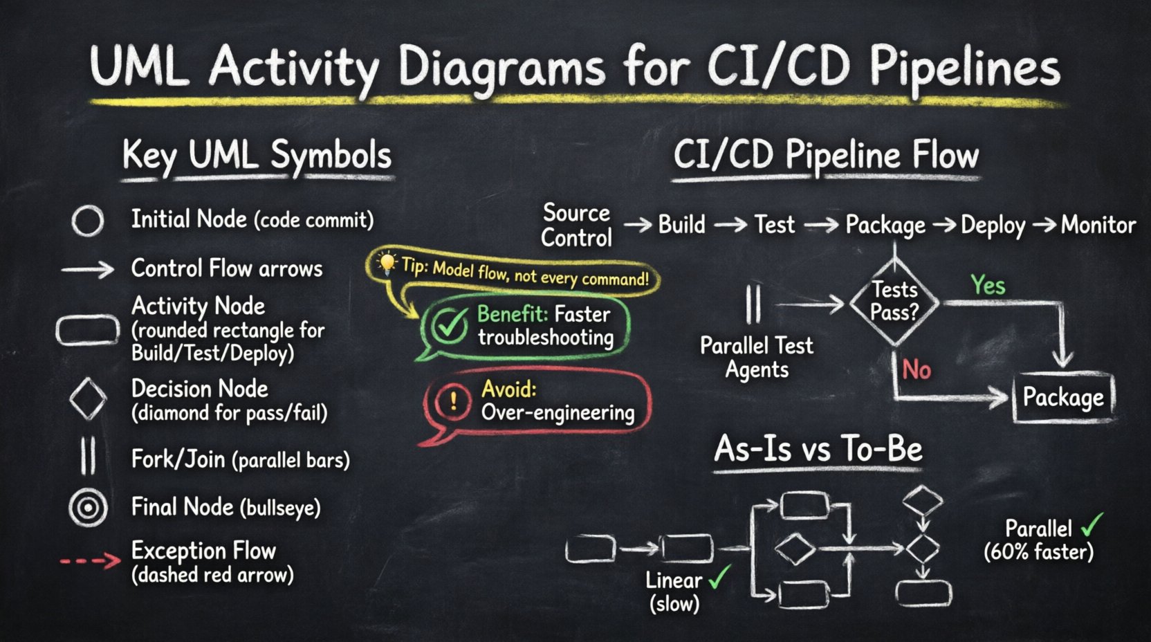
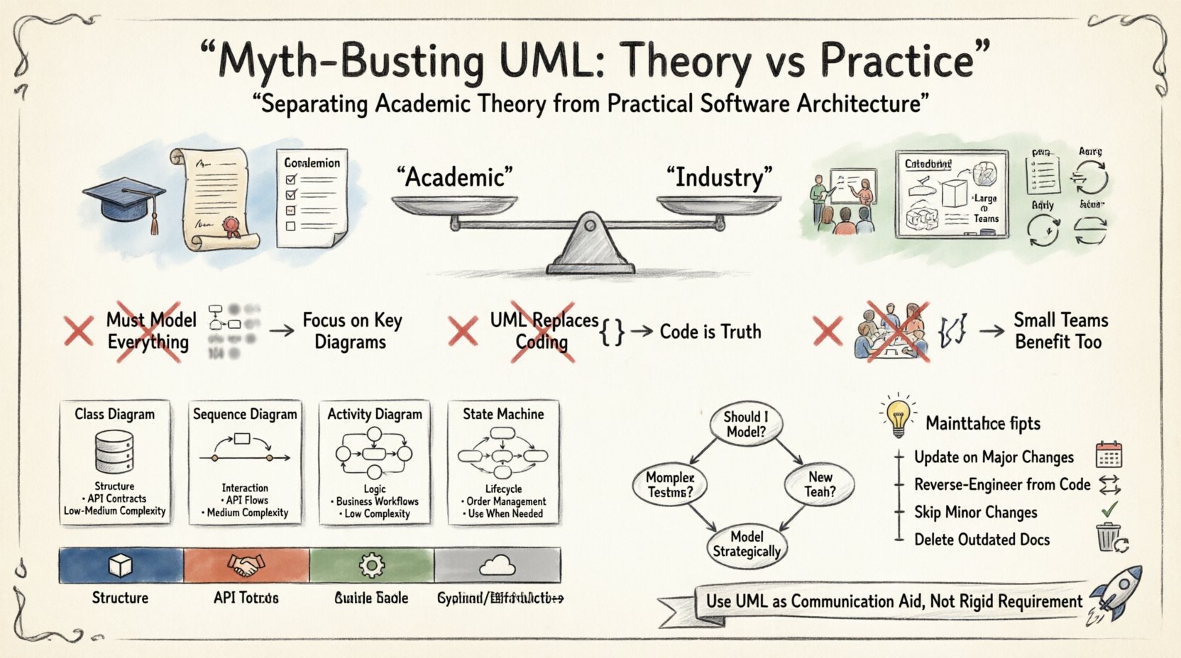
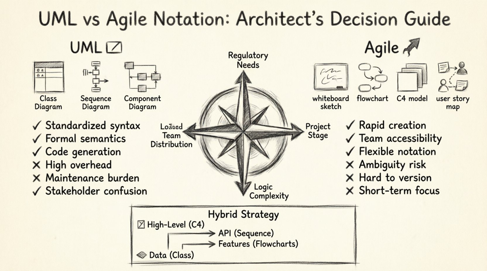
Complex software systems require more than just code. They require a blueprint. A vision that stakeholders can understand and developers can execute. Senior architects face a critical choice when designing these systems: strict standardization or rapid iteration. This decision shapes the documentation strategy, the communication flow, and the long-term maintainability of the project. The debate […]

UML

Future Outlook of UML: Will Traditional Diagrams Survive the Rise of AI-Generated Code?

The Unified Modeling Language (UML) has served as the standard for software architecture documentation for over three decades. It provided a common visual vocabulary for developers, architects, and stakeholders. However, the landscape is shifting rapidly. Artificial Intelligence now generates functional code from natural language prompts. This technological leap forces a critical question: Does the traditional

DFD

Interactive DFDs: Leveraging Digital Tools for Better Collaboration

Data Flow Diagrams (DFDs) have long served as the backbone of system analysis and design. Traditionally, these diagrams were static representations, often created on paper or isolated within rigid software environments. While they provided a snapshot of data movement, they frequently struggled to keep pace with the dynamic nature of modern development cycles. Today, the

DFD

Deep Dive into Hierarchical Data Flow Diagrams

In the complex landscape of system analysis and software engineering, clarity is the most valuable asset. When dealing with intricate business processes or large-scale information systems, a single static map often fails to capture the necessary detail. This is where the Hierarchical Data Flow Diagram becomes indispensable. By breaking down complex systems into manageable layers,

UML

Common Mistakes in UML Component Diagrams: Preventing Over-Abstraction in Design Phases

Designing complex software systems requires a clear blueprint. Unified Modeling Language (UML) component diagrams serve as a critical tool for visualizing the structural organization of a system. They represent the physical or logical building blocks of software, showing how components interact, depend on one another, and provide functionality. However, creating these diagrams is not merely

UML

Case Study: Leveraging UML Activity Diagrams to Streamline CI/CD Pipeline Workflows

In the modern landscape of software development, the speed and reliability of delivery are paramount. Organizations strive to release features rapidly while maintaining high stability. However, as pipelines grow in complexity, visualizing the flow of code from commit to production becomes increasingly difficult. This is where Unified Modeling Language (UML) Activity Diagrams prove invaluable. By

UML

The Complete Component Breakdown of UML Class Diagrams for Intermediate System Analysts

System analysis requires precision. When modeling software architecture, clarity is paramount. Unified Modeling Language (UML) Class Diagrams serve as the structural blueprint for object-oriented systems. They define the static structure of a system, outlining objects, their attributes, methods, and relationships. For intermediate analysts, moving beyond basic shapes into semantic depth is essential. This guide dissects

UML

Comprehensive Walkthrough of UML Timing Diagrams: Syncing Events Across Global Systems

Designing software for global deployment introduces a unique set of challenges, primarily centered around time. In distributed systems, latency, clock drift, and network delays can cause critical failures if not properly modeled. A UML Timing Diagram offers a specialized view for visualizing how objects change state over time. Unlike other diagrams that focus on flow,

UML

Definitive Overview of UML Interaction Overview Diagrams: Handling Nonlinear Control Flow

In modern software architecture, systems rarely follow a straight line. User actions branch, conditions change, and error handling loops back to previous states. When modeling these complex behaviors, standard Sequence Diagrams often fall short because they assume a linear progression of messages. This is where the UML Interaction Overview Diagram becomes essential. It provides a

Scroll to Top