

In the landscape of software architecture, choosing the right modeling language is not merely a stylistic preference; it is a foundational decision that impacts scalability, maintainability, and data integrity. Two dominant paradigms frequently emerge when discussing system design: Unified Modeling Language (UML) and Entity Relationship (ER) diagrams. While both serve to visualize complex systems, they approach the problem from fundamentally different angles. One focuses on behavior and structure in a general sense, while the other zeroes in on data persistence and relationships.
This guide provides a technical deep dive into these modeling techniques. We will explore their theoretical underpinnings, practical applications, and the critical junctures where transitioning between them becomes necessary for data-centric architectures. Understanding these distinctions allows architects to design systems that are robust against change and aligned with business logic.
The Purpose of UML in System Design 🛠️
Unified Modeling Language was established to provide a standard way of visualizing the design of a system. It is object-oriented in nature, designed to communicate the behavior of a system through various diagram types. In a data-centric context, the Class Diagram is often the primary concern, but it represents more than just data storage.
- Behavioral Focus: UML excels at describing how objects interact. Sequence diagrams and state machine diagrams illustrate the flow of control, which is often invisible in pure data models.
- Abstraction Levels: UML allows for modeling at the conceptual level, logical level, and physical level. This flexibility helps teams align on architecture before implementation details are finalized.
- Encapsulation: The object-oriented paradigm encourages encapsulating data and methods within classes. This reflects how application logic operates, rather than how the database stores it.
- Inheritance and Polymorphism: These concepts are native to UML class structures, allowing for complex inheritance hierarchies that do not always map cleanly to relational tables.
When designing a system where the primary value lies in the interaction between components, UML provides the necessary vocabulary. It captures the “how” of the system, ensuring that the logic governing the data is as clear as the data itself.
The Role of ER Diagrams in Data Modeling 🗄️
Entity Relationship diagrams are specialized tools designed specifically for defining and describing the data within a system. They predate UML in some contexts and remain the industry standard for database schema design. Their primary goal is to ensure data integrity and efficiency.
- Data-Centric View: ER diagrams treat data as the first-class citizen. They define entities (tables), attributes (columns), and relationships (foreign keys).
- Normalization: The modeling process often involves normalizing data to reduce redundancy. This is critical for maintaining consistency across large datasets.
- Cardinality Constraints: ER diagrams explicitly define one-to-one, one-to-many, and many-to-many relationships. These constraints are enforced at the database level, preventing invalid data states.
- Persistence Logic: They map directly to SQL structures. A well-designed ER diagram translates almost directly into a schema creation script.
For architectures where data integrity is the highest priority, such as financial systems or inventory management, ER diagrams provide the necessary rigor. They answer the question of “what” the system holds, rather than “how” it processes it.
Structural vs. Behavioral Focus 🧠
The core distinction lies in the scope of what is being modeled. UML is a general-purpose modeling language, whereas ER is domain-specific for data. Confusing the two can lead to architectural debt, where the database becomes a bottleneck or the application logic becomes overly complex.
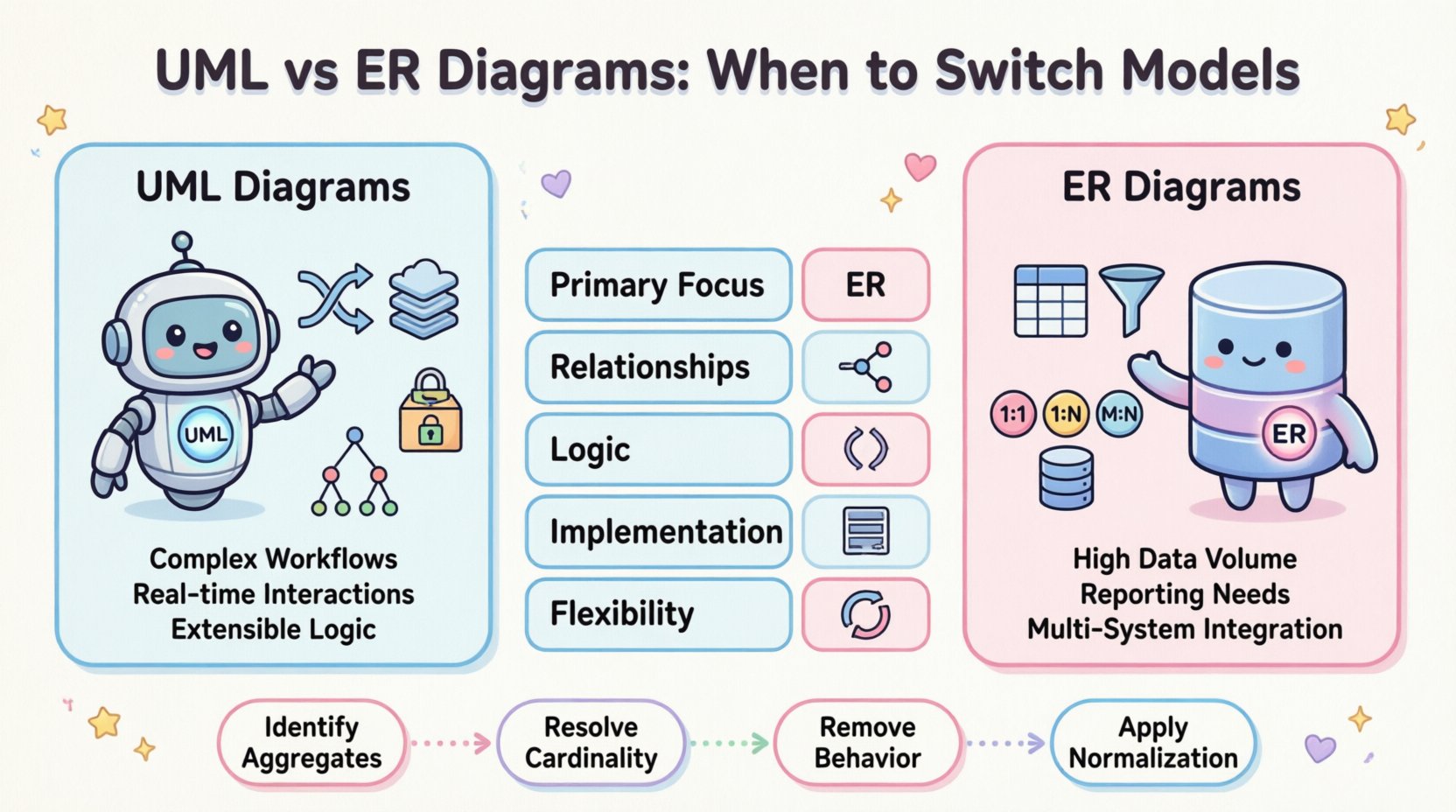
| Feature | UML (Class Diagram) | ER Diagram |
|---|---|---|
| Primary Focus | Object behavior and structure | Data relationships and integrity |
| Relationships | Associations, Aggregations, Compositions | Foreign Keys, Cardinality |
| Logic | Includes methods and behavior | Excludes logic, focuses on storage |
| Implementation | Maps to Object-Oriented Code | Maps to Relational Database Schema |
| Flexibility | High (polymorphism, inheritance) | Medium (constrained by SQL) |
Understanding this table is the first step in deciding when to utilize which model. A system that relies heavily on complex inheritance trees might suffer if forced into a rigid ER structure without an Object-Relational Mapping (ORM) layer. Conversely, a system requiring strict ACID compliance might suffer if the data model is obscured by object-oriented abstractions.
Identifying Data-Centric Requirements 🎯
Not all applications require the same level of data modeling. To determine if you need to switch models or prioritize one over the other, analyze the specific requirements of the project.
Indicators for UML Priority
- Complex Workflow: If the system involves multi-step processes with conditional branching, UML sequence diagrams clarify the flow better than static data models.
- Real-time Interaction: Systems requiring event-driven architectures benefit from UML state diagrams to manage the lifecycle of objects.
- Extensibility: If the business logic is expected to change frequently while the data structure remains stable, UML allows for easier refactoring of the application layer.
Indicators for ER Priority
- High Data Volume: When dealing with millions of records, data normalization and indexing strategies (visible in ER) become more critical than object behavior.
- Reporting Needs: If the primary output is analytical or reporting-based, a normalized ER model ensures query performance and accuracy.
- Multi-System Integration: When multiple applications need to access the same data, a shared ER schema provides a single source of truth.
When to Switch from UML to ER Models 🔄
Architects often start with a high-level UML model to establish the domain. However, as the project moves towards implementation, a shift to ER diagrams is often required. This transition is not about discarding the UML work but refining it for the persistence layer.
The Transition Phase
- Identify Aggregates: In UML, objects are grouped into aggregates. In ER, these must be broken down into tables based on foreign key relationships.
- Resolve Cardinality: UML associations are often vague (e.g., “many”). ER diagrams require precise cardinality (e.g., 1:1, 1:N, M:N). This step forces clarity on data ownership.
- Remove Behavioral Logic: UML classes often contain methods. These must be stripped out during the ER modeling phase, as databases store state, not behavior.
- Apply Normalization: Review the UML structure for redundancy. What looks like a clean class in UML might violate Third Normal Form (3NF) in an ER diagram.
Common Pitfalls During Transition
- Over-Normalization: Creating too many tables can lead to complex joins that degrade performance. Balance normalization with query efficiency.
- Loss of Context: Sometimes, the semantic meaning of a relationship is lost when moving from UML associations to ER foreign keys. Documentation must be updated to reflect this.
- Ignoring Inheritance: Relational databases do not support inheritance natively. UML inheritance hierarchies must be mapped to table structures (e.g., single table inheritance vs. joined table inheritance).
Managing Object-Relational Impedance 🔄
One of the most significant challenges in data-centric architectures is the impedance mismatch between the object-oriented world of UML and the relational world of ER diagrams. This gap exists because objects are dynamic and hierarchical, while relational tables are static and flat.
- Graph vs. Tree: UML models often represent complex graphs of objects. ER models represent tree structures of tables. Bridging this requires careful design of foreign keys.
- Identity Management: UML uses object references. ER uses primary keys. Ensuring these identities align throughout the lifecycle of the system is vital.
- Data Integrity: UML relies on runtime checks. ER relies on schema constraints. Switching models requires shifting the burden of validation from the application code to the database engine.
When this impedance is ignored, the system suffers from “anemic domain models” where the business logic is pushed into the database, or “impedance-induced complexity” where the application struggles to map data back to objects.
Normalization and Cardinality Rules 📏
While UML allows for flexibility in how entities relate, ER diagrams enforce strict rules to maintain data quality. Understanding these rules is essential when switching models.
Cardinality Constraints
- One-to-One: A single record in Table A relates to exactly one record in Table B. Common in user profiles or configuration settings.
- One-to-Many: One record in Table A relates to multiple records in Table B. This is the most common relationship in relational databases (e.g., Orders to OrderItems).
- Many-to-Many: Multiple records in Table A relate to multiple records in Table B. ER diagrams resolve this through a junction table (associative entity).
Normalization Forms
When converting a UML class structure to an ER diagram, apply normalization to eliminate anomalies.
- 1NF: Atomic values. No repeating groups in a column.
- 2NF: No partial dependencies. All non-key attributes must depend on the whole primary key.
- 3NF: No transitive dependencies. Non-key attributes should not depend on other non-key attributes.
Failing to apply these rules during the switch from UML can result in data redundancy and update anomalies, which are difficult to rectify once data is populated.
Maintenance and Evolution Strategies 🛡️
Once the model is established, the architecture must evolve. Both UML and ER diagrams require maintenance, but the cost of change differs.
- Schema Migration: Changing an ER diagram often requires database migration scripts. This is a higher-friction process than changing UML class definitions.
- Refactoring: UML allows for easier refactoring of the application logic without touching the database. ER changes require careful planning to avoid downtime.
- Versioning: It is crucial to version both diagrams. As the system grows, the data model may diverge from the initial UML design. Documentation must track these changes.
Adopting a strategy where the ER diagram is the source of truth for data, while UML remains the source of truth for behavior, often yields the best results. This separation of concerns keeps the data layer stable while allowing the application layer to iterate rapidly.
Collaborative Workflows for Architects 🤝
Effective modeling is a team effort. Developers, database administrators, and business analysts often have different views of the system.
- Unified Vocabulary: Ensure all stakeholders understand the symbols used in both UML and ER diagrams. Ambiguity leads to implementation errors.
- Iterative Design: Start with a high-level UML model to capture requirements. Refine it into an ER diagram for the database team. Iterate between the two as requirements change.
- Code Generation: Some tools allow generating SQL from ER diagrams or code from UML Class Diagrams. While convenient, these should be reviewed manually to ensure architectural intent is preserved.
Conclusion on Model Selection
Selecting between UML and ER diagrams is not a binary choice but a strategic decision based on the system’s primary needs. For data-centric architectures, the ER diagram provides the necessary guardrails for integrity and performance. However, UML remains indispensable for defining the behavior and interactions that drive the data.
By understanding the strengths and limitations of each, architects can switch models at the appropriate time, ensuring that the application logic and the data storage work in harmony. This alignment reduces technical debt and supports long-term system evolution without sacrificing clarity or performance.