

Creating a Data Flow Diagram (DFD) often begins with identifying the primary processes and data stores of a system. However, as system complexity grows, simple Level 0 or Level 1 diagrams frequently fail to capture the necessary nuance. Advanced modeling requires a deeper understanding of decomposition, consistency, and error handling. This guide explores the techniques required to build robust, maintainable, and accurate data flow representations without relying on specific tools.
High-fidelity DFDs serve as the backbone for system analysis. They bridge the gap between business requirements and technical implementation. When executed at a high level, these models reduce ambiguity and prevent costly rework during the development phase. The following sections detail specific strategies for enhancing the quality and utility of your diagrams.
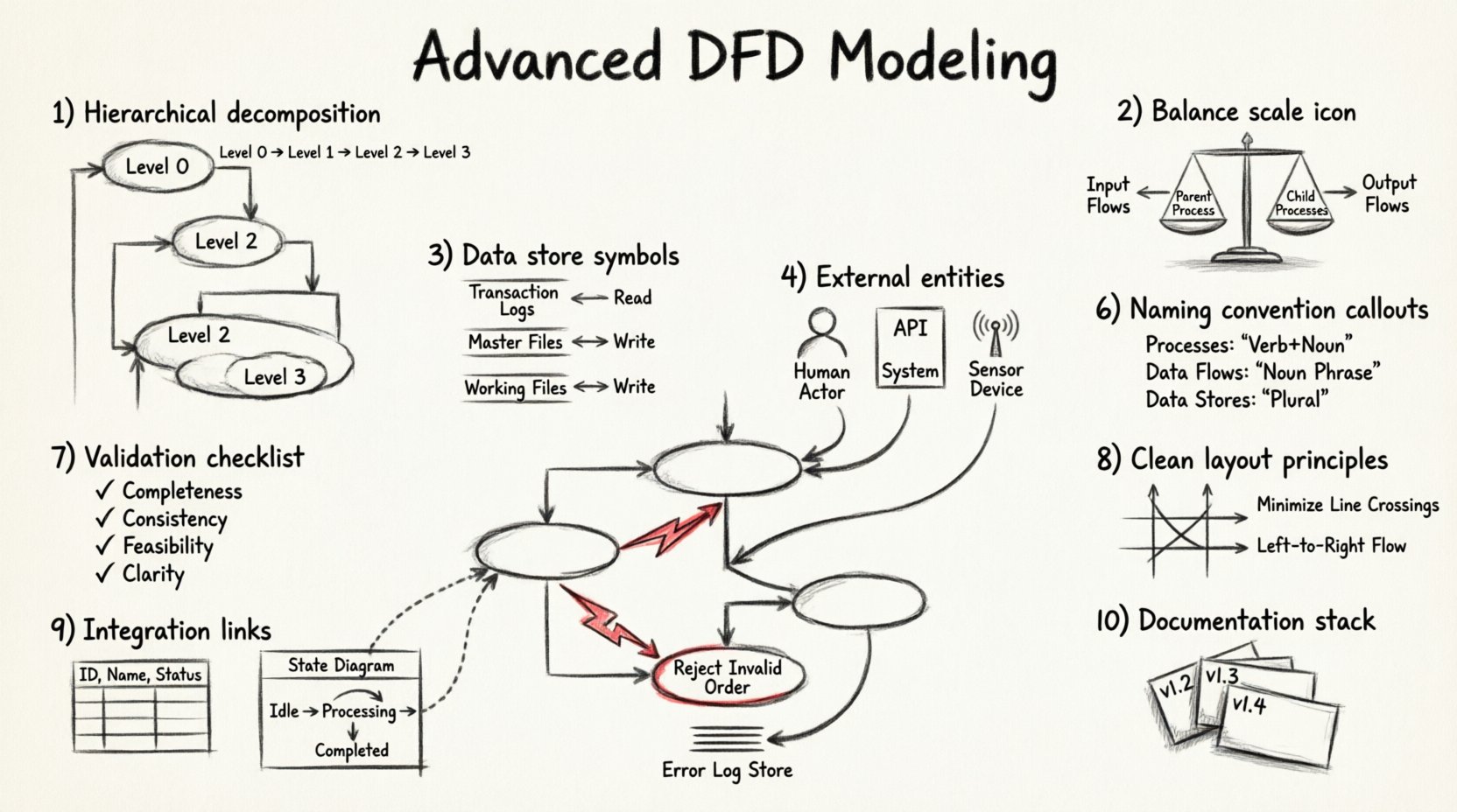
1. Hierarchical Decomposition Strategies 🧩
Decomposition is the process of breaking down a complex process into smaller, more manageable sub-processes. While basic modeling stops at Level 2, advanced analysis often requires reaching Level 3 or Level 4 to ensure every transformation is clear.
Why Decompose Further?
- Clarity: A single bubble representing a complex calculation may confuse stakeholders. Breaking it down reveals the logic steps.
- Traceability: Specific data transformations become easier to trace when they are isolated in their own processes.
- Scope Management: It helps in assigning responsibilities to different teams or modules within the architecture.
Techniques for Effective Decomposition
- Functional Grouping: Group related tasks under a parent process. For example, a “Process Order” bubble might decompose into “Validate Payment”, “Check Inventory”, and “Generate Invoice”.
- Logical Sequence: Ensure the sub-processes follow a chronological or logical order. Data should flow from input to output without circular dependencies at the same level.
- Granularity Balance: Avoid over-decomposition where a process becomes too trivial. Each sub-process should perform a distinct, meaningful function.
When creating child diagrams, ensure that the inputs and outputs of the parent process match the aggregate of the child processes. This principle is known as balancing, and it is critical for maintaining integrity across levels.
2. Balancing Inputs and Outputs ⚖️
One of the most common errors in DFD modeling is the loss of data flow when moving from a parent diagram to a child diagram. Balancing ensures that no data is created or destroyed during decomposition.
The Balancing Rule
Every data flow entering the parent process must enter at least one child process. Conversely, every data flow leaving the parent process must originate from at least one child process. If a flow appears in a child diagram but not the parent, or vice versa, the model is unbalanced.
Common Balancing Errors
- Missing Inputs: A sub-process requires data that is not provided by any input flow in the parent.
- Orphan Outputs: A sub-process generates data that is not passed up to the parent level.
- Hidden Flows: Data passes through an internal process but is not represented as a flow in the parent diagram.
To verify balance, draw a vertical line through the parent process. List all inputs and outputs on the left and right sides. Compare this list to the aggregated inputs and outputs of the child diagram. They must match exactly.
3. Managing Data Stores Deeply 💾
Data stores represent repositories where information is held for later use. In advanced modeling, the distinction between temporary storage and permanent storage, as well as the nature of access, becomes significant.
Types of Data Stores
- Transaction Logs: Stores used for auditing and history. They typically receive write-only or append-only flows.
- Master Files: Central repositories of reference data, such as customer records or product catalogs. These often receive read and write flows.
- Working Files: Temporary storage used during a specific process. These might be discarded after the process completes.
Access Patterns
It is crucial to distinguish between reading from a store and writing to it. A single flow can represent a read, a write, or both. However, advanced diagrams often separate these to clarify the intent.
- Read Access: Indicates the process retrieves data for analysis or display. This flow points toward the process.
- Write Access: Indicates the process updates or creates data. This flow points away from the process.
| Access Type | Flow Direction | Use Case |
|---|---|---|
| Read | Store → Process | Validation, Lookup, Display |
| Write | Process → Store | Update, Save, Log, Archive |
| Update | Bi-directional | Modify Existing Record |
4. External Entities and Interactions 👥
External entities represent sources or destinations of data outside the system boundary. In advanced modeling, these are not just “users” but can include other systems, hardware devices, or regulatory bodies.
Refining Entity Definitions
- Human Actors: Defined by their role, such as “Administrator” or “Customer”, rather than specific individuals.
- Automated Systems: Interfaces with other software or APIs. These often require specific protocol data flows.
- Physical Devices: Sensors or printers that interact with the system via data streams.
Interaction Complexity
Complex interactions often involve multiple entities communicating through the system. Ensure that every external entity has at least one data flow entering or leaving the system. An entity with no connections is likely a modeling error.
When modeling system-to-system communication, consider the volume and frequency of data flows. High-volume flows may require different architectural considerations than low-volume control signals.
5. Exception and Error Pathways 🚨
Standard DFDs often focus on the “happy path”—the ideal flow of data where everything works correctly. Advanced modeling requires explicit representation of error handling and exception paths.
Representing Errors
- Failure Flows: Data flows that represent error messages or status codes returned to the source.
- Exception Processes: Specific bubbles that handle invalid inputs, such as “Reject Invalid Order” or “Notify Security Team”.
- Data Stores for Errors: Logs that record failed transactions for debugging or auditing purposes.
Why Include Errors?
Omitting error paths leads to incomplete system requirements. Developers may assume inputs are always valid, leading to fragile code. Including these paths ensures that the system is robust.
For example, if a payment process fails, the flow should indicate that the data returns to the “Customer” entity with a notification, rather than simply disappearing. This clarifies the user experience and system behavior under stress.
6. Naming Conventions and Standards 🏷️
Consistency in naming is vital for maintainability. Ambiguous names lead to misinterpretation of the system logic.
Process Names
- Always use a Verb followed by a Noun.
- Example: “Calculate Tax” instead of “Tax”.
- Example: “Update Customer Record” instead of “Update”.
Data Flow Names
- Use Noun Phrases that describe the data being moved.
- Example: “Invoice Details” instead of “Bill”.
- Example: “Authentication Token” instead of “Key”.
Data Store Names
- Use plural nouns to indicate a collection of records.
- Example: “Orders” instead of “Order”.
- Example: “User Profiles” instead of “Profile”.
Adhering to these conventions reduces cognitive load for anyone reviewing the diagram. It also facilitates communication between business analysts and technical teams.
7. Validation and Quality Assurance ✅
Once the model is drafted, a rigorous review process is necessary to ensure accuracy. This involves checking against specific criteria to identify logical gaps.
Validation Checklist
- Completeness: Are all requirements represented?
- Consistency: Do names and definitions match across diagrams?
- Feasibility: Can the described flows exist within the technical constraints?
- Clarity: Is the diagram easy to read and understand?
Common Pitfalls
| Pitfall | Impact | Correction |
|---|---|---|
| Black Hole | Data enters a process but no output leaves. | Ensure data is transformed or stored. |
| Gray Hole | Outputs do not match inputs logically. | Verify transformation logic. |
| Spontaneous Generation | Data appears without a source. | Identify the origin of the data. |
| Data Cycle | Data flows in a loop without change. | Break the cycle or define a stopping condition. |
8. Visual Layout Principles 🎨
While DFDs are logical models, their visual presentation affects how well they are understood. A cluttered diagram obscures the logic.
Layout Guidelines
- Minimize Crossings: Arrange processes to reduce the number of lines that cross each other.
- Group Related Items: Keep related processes and data stores close together to indicate logical grouping.
- Use White Space: Allow breathing room around nodes to prevent visual fatigue.
- Consistent Orientation: Ensure data flows generally move from left to right or top to bottom where possible.
When diagrams become too large, use context diagrams to show high-level boundaries and then drill down into sub-diagrams. This keeps each view manageable.
9. Integration with Other Models 🔗
Data Flow Diagrams rarely exist in isolation. They are often part of a larger system design package that includes Entity-Relationship Diagrams (ERD) and State Transition Diagrams.
Alignment with ERD
Data stores in the DFD should correspond to tables or entities in the ERD. Ensure that the attributes required by the processes exist in the database schema. Discrepancies here indicate a gap in the data model.
Alignment with State Diagrams
While DFDs focus on data movement, state diagrams focus on object behavior. A process in a DFD might trigger a state change in a state diagram. Aligning these ensures that the system responds correctly to data inputs.
10. Final Considerations for Complex Systems 🏗️
As systems scale, the number of DFDs can become unmanageable. It is important to maintain a structured documentation strategy.
Documentation Management
- Version Control: Track changes to diagrams over time to understand evolution.
- Cross-Referencing: Link related diagrams using clear identifiers (e.g., DFD-01, DFD-01.1).
- Metadata: Include author, date, and review status on every diagram.
Advanced modeling is not about creating the most complex diagram possible. It is about creating the most accurate representation of the system logic. By focusing on decomposition, balancing, error handling, and consistent naming, analysts can produce models that truly serve the project.
Remember that a diagram is a communication tool. If the stakeholders cannot understand the flow of data, the model has not succeeded. Regular reviews with business users ensure the technical details remain aligned with operational needs.