

In the landscape of system design and software engineering, selecting the appropriate modeling notation is a critical decision. It dictates how requirements are captured, how logic is visualized, and how information flows between stakeholders. Two dominant methodologies stand out: the Data Flow Diagram (DFD) and the Unified Modeling Language (UML). While both aim to represent system behavior, they approach the problem from fundamentally different perspectives.
Understanding the distinction is not merely academic; it impacts the clarity of documentation, the efficiency of development, and the maintainability of the final product. This guide explores the technical nuances of both approaches, providing a framework for selecting the right tool for your specific analysis needs.
Understanding Data Flow Diagrams (DFD) 📈
The Data Flow Diagram is a structured analysis technique. It originated in the late 1960s alongside Structured Systems Analysis and Design Method (SSADM). Its primary focus is on the flow of information through a system. Unlike code-centric models, DFDs describe what the system does, rather than how it is implemented.
Core Components of a DFD
A DFD is constructed using a specific set of symbols. Each element serves a distinct purpose in mapping data movement:
- External Entities: Represented by rectangles, these are sources or destinations of data outside the system boundaries. Examples include users, other systems, or hardware devices.
- Processes: Shown as circles or rounded rectangles, these transform input data into output data. They represent the functional logic or business rules.
- Data Stores: Depicted as open-ended rectangles, these indicate where data is held at rest. This includes databases, files, or archives.
- Data Flows: Arrows connecting the elements. These show the direction of data movement and the name of the data being transferred.
Levels of Decomposition
DFDs are hierarchical. They allow analysts to zoom in on specific areas of the system:
- Context Diagram (Level 0): A high-level view showing the system as a single process and its interaction with external entities. It defines the boundaries.
- Level 1 Diagram: Breaks the main process into major sub-processes. It shows the major data flows between these functions and data stores.
- Level 2 Diagram: Further decomposes specific Level 1 processes into detailed logic steps. This level is often used for defining specific functional requirements.
When to Use DFD
DFDs are particularly effective when the primary concern is the movement of data through a complex process. They excel in scenarios where:
- Data Integrity is Paramount: You need to ensure every data point is accounted for from entry to storage.
- Legacy Systems are Being Analyzed: Older mainframe or transaction processing systems often rely on structured logic best represented by data flow.
- Business Process Re-engineering: When optimizing workflows, seeing where data waits or where bottlenecks occur is crucial.
- Non-Technical Stakeholders: The symbols are often easier for business analysts to interpret than object-oriented structures.
Understanding Unified Modeling Language (UML) 🏗️
Unified Modeling Language emerged in the 1990s as a standard for object-oriented software design. It was created to consolidate various notations into a single, comprehensive language. UML focuses on the structure of the system and the interactions between objects. It is less concerned with the flow of data and more concerned with the behavior and state of system components.
Core Diagram Types in UML
UML is a suite of diagrams, each serving a specific modeling purpose. The most common types include:
- Use Case Diagram: Describes the functional requirements from the perspective of actors (users). It maps interactions between actors and system functions.
- Class Diagram: The backbone of the system structure. It defines classes, attributes, methods, and relationships (inheritance, association, aggregation).
- Sequence Diagram: Illustrates object interactions over time. It shows how messages are passed between objects to achieve a specific result.
- Activity Diagram: Similar to a flowchart, this models the flow of control from activity to activity. It is useful for complex conditional logic.
- State Machine Diagram: Describes the lifecycle of an object. It shows the states an object can be in and the events that trigger transitions.
When to Use UML
UML is the standard for modern application development, particularly when using object-oriented programming languages. It is preferred when:
- Object-Oriented Design is Required: The codebase relies heavily on classes, inheritance, and polymorphism.
- Complex Interactions: The system requires detailed tracking of message passing and timing between components.
- Scalability Planning: You need to model how different parts of the system relate structurally to support future growth.
- Agile Development: UML diagrams can be generated directly from code or used to plan sprints in iterative cycles.
Key Differences: A Structured Comparison
To clarify the distinctions, we can analyze the two methodologies across several dimensions. This comparison helps in identifying which approach aligns with your project goals.
| Feature | Data Flow Diagram (DFD) | Unified Modeling Language (UML) |
|---|---|---|
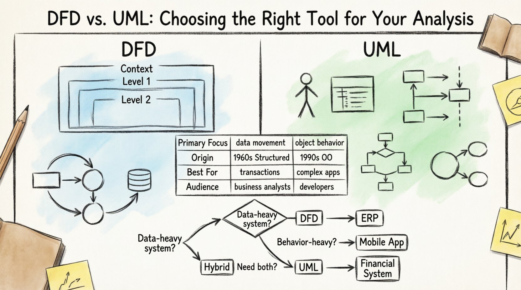
| Primary Focus | Data movement and transformation | Object structure and behavior |
| Methodology Origin | Structured Analysis (Procedural) | Object-Oriented Design |
| System Boundary | Clear external entities vs. internal processes | Classes and Interfaces |
| Data Persistence | Explicit Data Stores | Attributes within Classes |
| Best Suited For | Transaction systems, Batch processing | Complex applications, GUIs, Distributed systems |
| Stakeholder Audience | Business Analysts, Functional Managers | Software Architects, Developers |
Deep Dive: Decision Framework 🧭
Choosing between these tools often depends on the specific phase of the project lifecycle and the nature of the problem domain. Below are detailed scenarios to guide your decision.
Scenario 1: Enterprise Resource Planning (ERP) Implementation
When implementing a large-scale ERP system, the focus is often on data consistency and process compliance. The system must handle massive amounts of transactional data moving between modules like finance, inventory, and HR.
- Recommended Approach: DFD.
- Reasoning: The integrity of the data flow is the highest priority. You need to ensure that a sales order triggers the correct inventory deduction and financial posting. DFDs visualize these dependencies clearly without getting bogged down in class hierarchy details.
Scenario 2: Mobile Application Development
Developing a mobile application requires managing user interface states, network requests, and local data storage. The interaction is highly dynamic and event-driven.
- Recommended Approach: UML.
- Reasoning: State Machine and Sequence diagrams are essential here. You need to model how a user navigates screens, how the app handles offline states, and how data is cached locally. UML captures the state transitions that DFD cannot.
Scenario 3: Financial Reporting System
This system involves complex calculations based on historical data. The logic is rule-based and deterministic.
- Recommended Approach: Hybrid.
- Reasoning: Use DFD to map the calculation pipelines and data sources. Use UML Class Diagrams to define the data structures and objects that hold the calculated results. This combination ensures both the logic flow and the data structure are documented.
Integration with the Software Development Lifecycle (SDLC)
Both modeling techniques must integrate seamlessly into the broader development process. Their value lies in reducing ambiguity before code is written.
Requirements Gathering Phase
During this phase, the goal is to understand what the system must do.
- DFD Role: Helps define the scope. The Context Diagram is excellent for agreeing on system boundaries with clients.
- UML Role: Use Case Diagrams help identify who is interacting with the system and what functions are required.
Design Phase
Here, the abstract requirements are translated into technical specifications.
- DFD Role: Level 1 and 2 diagrams serve as blueprints for database schema design. They highlight where data is stored and retrieved.
- UML Role: Class diagrams directly translate to code structures. Sequence diagrams assist in defining API contracts between microservices.
Testing Phase
Validation ensures the system meets the design.
- DFD Role: Test cases can be derived from data flows to ensure all paths are covered (e.g., ensuring no data is lost in a specific process).
- UML Role: State diagrams help in testing state transitions (e.g., ensuring an order cannot be canceled after it has been shipped).
Common Pitfalls in Modeling ⚠️
Even with the right tool, modeling can go wrong. Recognizing common errors helps maintain the quality of your documentation.
Pitfall 1: The Control Flow vs. Data Flow Confusion
A frequent error in DFDs is confusing control logic with data movement. DFDs do not show loops, decisions, or control flow. They only show data. If a process stops based on a condition, that condition must be noted in the process description, not drawn as a diamond shape (which belongs to flowcharts).
Pitfall 2: Over-Modeling in UML
UML can become overwhelming. Creating a Class Diagram with hundreds of classes without a clear hierarchy adds complexity rather than clarity. Focus on the core domain model. Not every attribute needs a diagrammatic representation in the early stages.
Pitfall 3: Inconsistent Notation
Using a mix of symbols (e.g., Gane and Sarson vs. Yourdon and DeMarco for DFDs) within the same document confuses readers. Choose a standard and stick to it throughout the project lifecycle.
Pitfall 4: Ignoring the Data Dictionary
For DFDs, a Data Dictionary is essential. Without it, the names on the data flows (e.g., “Customer Info”) are ambiguous. Define data types, formats, and lengths in a companion document.
Best Practices for Documentation 📝
To ensure your modeling efforts yield value, adhere to these operational standards.
- Keep Diagrams Current: Documentation decays rapidly. If the code changes, the diagram must change. Treat diagrams as code artifacts, not static Word documents.
- Version Control: Store your model files in the same repository as your source code. Use version control to track changes in logic over time.
- Limit Depth: Do not decompose processes indefinitely. If a Level 3 diagram becomes unreadable, stop. The goal is clarity, not exhaustive detail.
- Use Whiteboards for Collaboration: Before finalizing models, sketch them on a whiteboard. This encourages feedback and reduces the time spent drawing perfect diagrams.
- Automate Where Possible: Modern tools can generate diagrams from code or generate code from diagrams. Leverage this bidirectional capability to keep models in sync.
Maintenance and Long-Term Value
The true test of a modeling tool is how well it supports the system after deployment.
Impact on Onboarding
New developers joining a project need to understand the architecture quickly. A well-maintained UML Class Diagram provides a map of the codebase. A well-maintained DFD helps them understand the data pipeline. Both reduce the time to productivity.
Impact on Refactoring
When refactoring, understanding dependencies is key. UML dependency diagrams help identify which classes are tightly coupled. DFDs help identify which data stores are heavily utilized, guiding database optimization.
Impact on Auditing
In regulated industries (Finance, Healthcare), audit trails are mandatory. DFDs are excellent for demonstrating data lineage. They prove exactly where data comes from, how it is transformed, and where it is stored, satisfying compliance requirements.
Summary of Selection Criteria
There is no single “best” tool. The choice depends on the context of your project. Consider the following checklist:
- Is the system data-heavy? Lean towards DFD.
- Is the system behavior-heavy? Lean towards UML.
- Are you building a new OO application? Use UML.
- Are you analyzing a legacy procedural system? Use DFD.
- Do you need to communicate with non-technical stakeholders? DFD is often more accessible.
- Do you need to communicate with developers? UML is the industry standard.
By carefully evaluating these factors, you ensure that your modeling effort adds value rather than becoming a bureaucratic hurdle. Whether you choose the structured clarity of Data Flow Diagrams or the structural rigor of Unified Modeling Language, the goal remains the same: clear communication and robust system design.