

Large-scale software systems and complex organizational processes rely heavily on clear visual communication. When data moves across multiple departments, systems, or microservices, the risk of misunderstanding increases exponentially. This is where the Data Flow Diagram (DFD) becomes an indispensable tool. However, creating a static diagram is only the beginning. The real value lies in refining data flow diagrams to ensure accuracy, scalability, and maintainability as the project grows.
Refining a DFD is not merely about redrawing boxes; it is about validating the logic of information movement, ensuring data integrity, and aligning technical architecture with business goals. In complex environments, a poorly maintained diagram can lead to integration failures, data loss, and significant rework. This guide provides a comprehensive framework for managing DFDs throughout the lifecycle of a large-scale project.
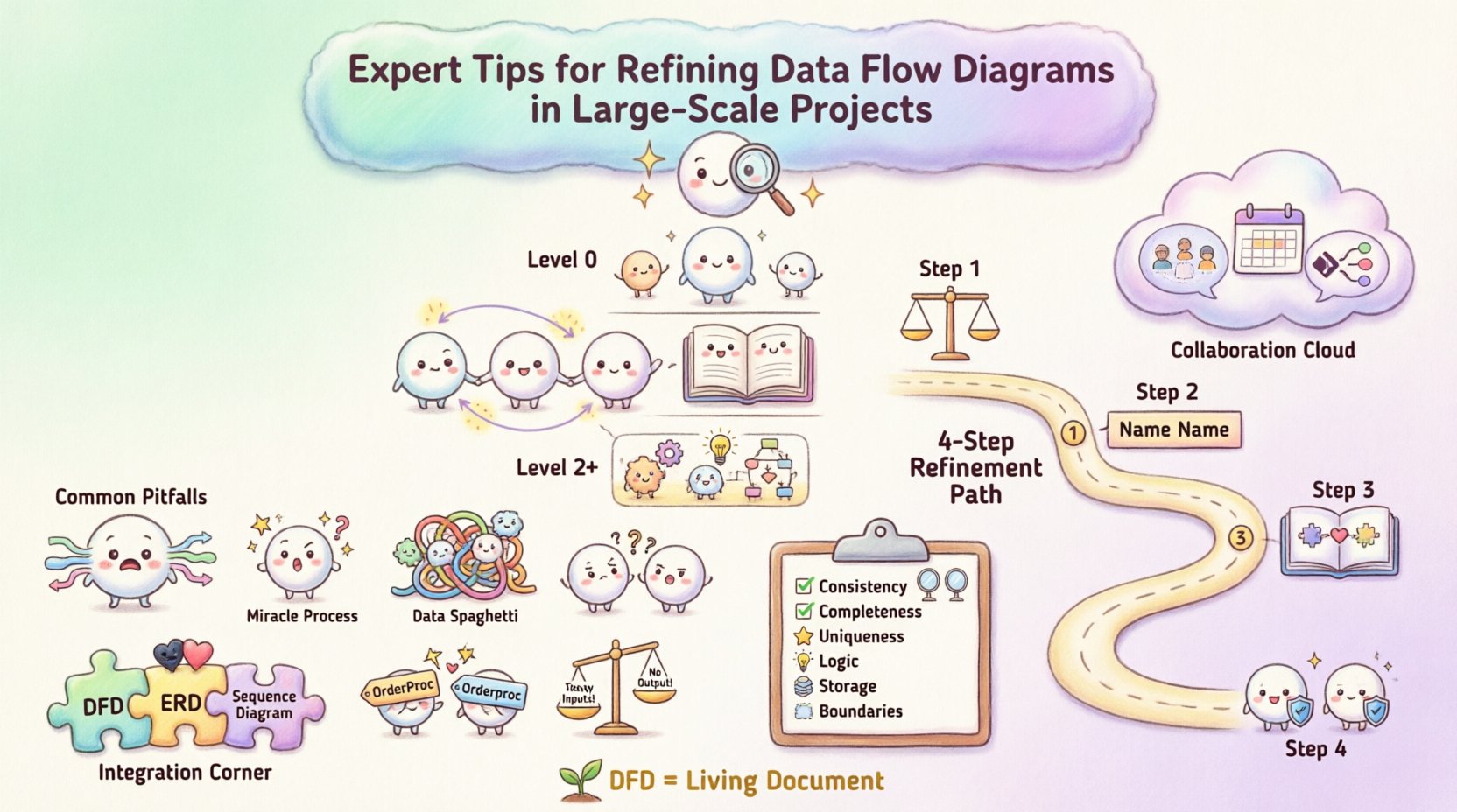
🏗️ Understanding the Hierarchy of Diagram Levels
Before diving into refinement, one must understand the structural hierarchy. A robust DFD strategy relies on decomposition. You cannot map every single data interaction in a massive system on a single page. Instead, you use levels to manage complexity.
1. Context Diagram (Level 0)
The context diagram provides the high-level overview. It represents the entire system as a single process bubble. It identifies external entities (sources or sinks of data) and the major data flows entering or leaving the system boundary. This level is crucial for stakeholder alignment because it avoids technical noise.
- Focus: System boundaries and external interactions.
- Complexity: Low. One process, multiple entities.
- Refinement Goal: Ensure no hidden processes exist that bypass the boundary.
2. Level 1 DFD
This level decomposes the single process from the context diagram into major sub-processes. It reveals the internal structure without getting bogged down in granular details. This is often the primary map for architects.
- Focus: Major functional areas.
- Complexity: Medium. Multiple processes, data stores, and flows.
- Refinement Goal: Ensure balancing (inputs/outputs match context).
3. Level 2 and Below
These diagrams drill down into specific sub-processes. In large-scale projects, you may have multiple Level 2 diagrams for different modules. This is where the most detailed logic resides.
- Focus: Granular logic and data transformations.
- Complexity: High.
- Refinement Goal: Eliminate data redundancy and ensure logical flow.
🔍 Common Pitfalls in Large-Scale DFDs
As systems expand, diagrams often become cluttered or inconsistent. Identifying these issues early prevents downstream errors. Below are common anomalies found during the refinement phase.
| Anomaly | Description | Impact on Project |
|---|---|---|
| Black Hole | A process has inputs but no outputs. | Data is created and lost; logic is incomplete. |
| Miracle Process | A process has outputs but no inputs. | Implies data appears from nowhere; violates conservation. |
| Data Spaghetti | Excessive crossing lines between processes. | Diagram becomes unreadable; logic is unclear. |
| Inconsistent Naming | Same data has different names in different diagrams. | Confusion in development and testing phases. |
| Unbalanced Flows | Input/Output mismatch between parent and child diagrams. | Logical errors in system integration. |
During refinement, you must actively scan for these patterns. A diagram that looks visually appealing but contains a black hole is functionally useless. The goal is logical correctness over aesthetic simplicity.
🛠️ Step-by-Step Refinement Strategy
Refining a DFD is an iterative process. It requires moving back and forth between high-level abstraction and granular detail. Follow this structured approach to maintain control.
Step 1: Verify Balancing
The most critical rule in DFD refinement is balancing. Every data flow entering a parent process must be accounted for in the child processes, and vice versa. If a Level 0 diagram shows “Customer Order” entering the system, that same data must appear as an input in at least one Level 1 process.
- Check all data stores to ensure they are accessible.
- Ensure every process has at least one input and one output.
- Validate that data stores are not bypassed in high-level views.
Step 2: Standardize Naming Conventions
In large projects, multiple teams may work on different parts of the system. Without a unified naming standard, the diagram fragments. Establish a glossary for:
- Data Flows: Should be noun phrases (e.g., “Invoice Details”, not “Send Invoice”).
- Processes: Should be verb-object phrases (e.g., “Calculate Tax”, not “Tax”).
- Data Stores: Should be plural nouns representing the collection (e.g., “Orders”, not “Order”).
- External Entities: Should be singular nouns representing the source (e.g., “Customer”, not “Customers”).
Step 3: Consolidate Data Stores
As diagrams grow, it is tempting to create a new data store for every minor grouping. This leads to fragmentation. During refinement, merge redundant stores.
- If two stores hold the same entity type, combine them.
- Ensure the relationship between stores is clear (e.g., one-to-many).
- Avoid creating temporary stores that do not persist data.
Step 4: Define External Entities Clearly
External entities are often overlooked. In large-scale projects, you might interact with third-party APIs, legacy systems, or human operators. Treat these entities with the same rigor as internal processes.
- Specify the data format they expect (if known).
- Identify security requirements (authentication/encryption).
- Map the trust boundary for each entity.
🤝 Managing Complexity and Collaboration
Large-scale projects involve many stakeholders. A DFD is a communication tool as much as a design tool. If the diagram is too dense, it fails its purpose. If it is too abstract, it lacks utility.
Strategies for Stakeholder Alignment
- Use Layered Views: Provide business stakeholders with Level 0 diagrams. Provide developers with Level 2 diagrams.
- Regular Reviews: Schedule DFD review sessions before coding begins. Do not wait for the architecture to be frozen.
- Version Control: Treat diagrams as code. Maintain a history of changes so you can trace why a process was modified.
Handling Data Volume and Performance
Standard DFDs do not explicitly show performance metrics, but the flow of data implies load. During refinement, consider where bottlenecks might occur.
- Identify high-frequency data flows that might require caching.
- Look for processes that aggregate large datasets; these may need optimization.
- Ensure data stores are labeled with their retention policies if relevant.
📋 Validation Checklist for DFD Refinement
Before finalizing a diagram, run it through this validation checklist. This ensures consistency across the entire project documentation.
| Check | Pass Criteria |
|---|---|
| Consistency | Names match across all levels and documents. |
| Completeness | Every input has a corresponding process and output. |
| Uniqueness | No duplicate processes or data stores. |
| Logic | No data flows cross without a process transforming them. |
| Storage | Every data store has at least one read and one write flow. |
| Boundaries | External entities are clearly marked outside the system. |
🔄 Maintenance and Evolution
A DFD is not a one-time artifact. As the project evolves, the diagram must evolve with it. In large-scale initiatives, requirements change frequently. A static diagram becomes a liability if it does not reflect reality.
Change Management
When a new feature is added, update the diagram immediately. Do not treat diagram updates as a post-project task.
- Document the reason for the change.
- Identify which other diagrams are affected by the change.
- Notify the development team of the updated logic.
Refactoring the Diagram
Sometimes the structure of the system changes fundamentally. You may need to refactor the DFD itself. This is not a failure; it is a sign of a healthy system design process.
- Split complex processes into smaller, manageable sub-processes.
- Consolidate data stores if they become redundant.
- Remove obsolete flows that no longer exist in the live system.
🔗 Integrating DFDs with Other Models
DFDs do not exist in isolation. They often sit alongside Entity Relationship Diagrams (ERD) and Sequence Diagrams. Ensuring alignment between these models is a key part of refinement.
- DFD vs. ERD: Ensure every data store in the DFD has a corresponding table or entity in the ERD. If a DFD shows data being stored but the database schema lacks a field, the design is incomplete.
- DFD vs. Sequence Diagram: The DFD shows what data moves; the Sequence Diagram shows when and how. Ensure the order of operations in the sequence diagram matches the flow in the DFD.
🎯 Final Considerations for Success
Refining data flow diagrams is a discipline that requires patience and attention to detail. It is not about drawing pretty pictures; it is about defining the truth of how information moves through your organization. By adhering to strict naming conventions, maintaining balance between levels, and regularly validating against the checklist, you create a living document that supports development and reduces risk.
In large-scale projects, the cost of ambiguity is high. A refined DFD reduces that cost. It serves as a single source of truth for architects, developers, and business analysts. When everyone agrees on the data flows, the path to implementation becomes clearer and more efficient.
Remember that the diagram is a tool for thinking, not just for documentation. Use it to challenge assumptions. If a flow seems too simple, dig deeper. If a process seems too complex, decompose it. The refinement process itself often uncovers requirements that were previously hidden.
By following these guidelines, you ensure that your system design remains robust, understandable, and adaptable to future changes. This approach builds confidence in the architecture and facilitates smoother delivery of complex solutions.